
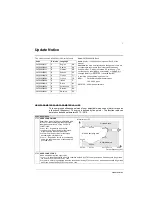


Update Notice
5
1004
JOGGING SEL
Defines the signal that activates the jogging function. Jogging uses Constant Speed 7 for speed reference and ramp
pair 2 for accelerating and decelerating. When the jogging activation signal is lost, the drive uses ramp stop to
decelerate to zero speed, even if coast stop is used in normal operation (parameter 2102). The jogging status can be
parameterized to relay outputs (parameter 1401). The jogging status is also seen in DCU Profile status bit 21.
0 =
NOT
SEL
– Disables the jogging function.
1 =
DI
1 – Activates/de-activates jogging based on the state of
DI
1 (
DI
1 activated = jogging active;
DI
1 de-activated =
jogging inactive).
2…6 =
DI
2…
DI
6 – Activates jogging based on the state of the selected digital input. See
DI
1 above.
-1 =
DI
1(
INV
) – Activates jogging based on the state of
DI
1 (
DI
1 activated = jogging inactive;
DI
1 de-activated = jogging
active).
-2…-6 =
DI
2(
INV
)…
DI
6(
INV
) – Activates jogging based on the state of the selected digital input. See
DI
1(
INV
) above.
1103
REF1 SELECT
20 =
KEYPAD
(
RNC
) – Defines the control panel as the reference source. A Stop command resets the reference to zero
(R stands for reset.). Changing the control source (
EXT
1 to
EXT
2,
EXT
2 to
EXT
1) does not copy the reference.
21 =
KEYPAD
(
NC
) – Defines the control panel as the reference source. A Stop command does not reset the reference
to zero. The reference is stored. Changing the control source (
EXT
1 to
EXT
2,
EXT
2 to
EXT
1) does not copy the
reference.
1401
RELAY OUTPUT 1
46 =
START
DELAY
– Energize relay when a start delay is active.
52 =
JOG
ACTIVE
– Energize relay when the jogging function is active.
1610
DISPLAY ALARMS
Controls the visibility of the following alarms:
• 2001, Overcurrent alarm
• 2002, Overvoltage alarm
• 2003, Undervoltage alarm
• 2009, Device overtemperature alarm.
For more information, see section
Alarm listing
.
0 =
NO
– The above alarms are suppressed.
1 =
YES
– All of the above alarms are enabled.
2101
START FUNCTION
8 =
RAMP
– Immediate start from zero frequency.
3023
WIRING FAULT
Defines the drive response to cross wiring faults and to ground faults detected when the drive is NOT running. When
the drive is not running, it monitors for:
• Improper connections of input power to the drive output (the drive can display fault 35,
OUTPUT
WIRING
if improper
connections are detected).
• Ground faults (the drive can display fault 16, earth fault if a ground fault is detected). Also, see parameter 3017
EARTH
FAULT
.
0 =
DISABLE
– No response to either of the above monitoring results.
1 =
ENABLE
– Displays a fault when this monitoring detects problems.
4010
SET POINT SEL
20 =
PID
2
OUT
– Defines PID controller 2 output (parameter 0127
PID
2
OUTPUT
) as the reference source.
Summary of Contents for ACH550-01
Page 1: ...ACH550 User s Manual ACH550 01 Drives 0 75 110 kW ACH550 UH Drives 1 150 HP ABB ...
Page 10: ...Update Notice 8 ...
Page 12: ......
Page 18: ...6 ACH550 User s Manual ...
Page 50: ...38 Preparing for installation ACH550 User s Manual ...
Page 325: ...313 ACH550 User s Manual ...
Page 358: ...346 ACH550 User s Manual ...
Page 409: ...Technical data 397 ACH550 User s Manual Frame size R1 IP54 UL Type 12 ...
Page 410: ...398 Technical data ACH550 User s Manual Frame size R2 IP54 UL Type 12 ...
Page 411: ...Technical data 399 ACH550 User s Manual Frame size R3 IP54 UL Type 12 ...
Page 412: ...400 Technical data ACH550 User s Manual Frame size R4 IP54 UL Type 12 ...
Page 413: ...Technical data 401 ACH550 User s Manual Frame size R5 IP54 UL Type 12 ...
Page 414: ...402 Technical data ACH550 User s Manual Frame size R6 IP54 UL Type 12 ...
Page 415: ...Technical data 403 ACH550 User s Manual Frame size R1 IP21 UL Type 1 ...
Page 416: ...404 Technical data ACH550 User s Manual Frame size R2 IP21 UL Type 1 ...
Page 417: ...Technical data 405 ACH550 User s Manual Frame size R3 IP21 UL Type 1 ...
Page 418: ...406 Technical data ACH550 User s Manual Frame size R4 IP21 UL Type 1 ...
Page 419: ...Technical data 407 ACH550 User s Manual Frame size R5 IP21 UL Type 1 ...
Page 420: ...408 Technical data ACH550 User s Manual Frame size R6 IP21 UL Type 1 ...
Page 453: ......


