


Parameter listing and descriptions
205
ACH550 User's Manual
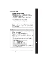
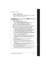
Group 16: SYSTEM CONTROLS
This group defines a variety of system level locks, resets and
enables.
Code Description
Range
1601
RUN ENABLE
-6…7
Selects the source of the Run enable signal. See the figure on page
.
0 =
NOT
SEL
– Allows the drive to start without an external Run enable
signal.
1 =
DI
1 – Defines digital input
DI
1 as the Run enable signal.
• This digital input must be activated for Run enable.
• If the voltage drops and de-activates this digital input, the drive will
coast to stop and not start until the Run enable signal resumes.
2…6 =
DI
2…
DI
6 – Defines digital input
DI
2…
DI
6 as the Run enable
signal.
• See
DI
1 above.
7 =
COMM
– Assigns the fieldbus Command Word as the source for the
Run enable signal.
• Bit 6 of Command Word 1 (parameter 0301) activates the Run
disable signal.
• See the fieldbus user’s manual for detailed instructions.
-1 =
DI
1(
INV
) – Defines an inverted digital input
DI
1 as the Run enable
signal.
• This digital input must be de-activated for Run enable.
• If this digital input activates, the drive will coast to stop and not start
until the Run enable signal resumes.
-2…-6 =
DI
2(
INV
)…
DI
6(
INV
) – Defines an inverted digital input
DI
2…
DI
6
as the Run enable signal.
• See
DI
1(
INV
) above.
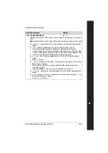
1602
PARAMETER LOCK
0…2
Determines if the control panel (operator keypad) can change
parameter values.
• This lock does not limit parameter changes made by macros.
• This lock does not limit parameter changes written by fieldbus inputs.
0 =
LOCKED
– You cannot use the control panel to change parameter
values.
• The lock can be opened by entering the valid pass code to
parameter 1603.
1 =
OPEN
– You can use the control panel to change parameter values.
2 =
NOT
SAVED
– You can use the control panel to change parameter
values, but they are not stored in permanent memory.
• Set parameter 1607
PARAM
SAVE
to 1 (
SAVE
) to store changed
parameter values to memory.
Summary of Contents for ACH550-01
Page 1: ...ACH550 User s Manual ACH550 01 Drives 0 75 110 kW ACH550 UH Drives 1 150 HP ABB ...
Page 10: ...Update Notice 8 ...
Page 12: ......
Page 18: ...6 ACH550 User s Manual ...
Page 50: ...38 Preparing for installation ACH550 User s Manual ...
Page 325: ...313 ACH550 User s Manual ...
Page 358: ...346 ACH550 User s Manual ...
Page 409: ...Technical data 397 ACH550 User s Manual Frame size R1 IP54 UL Type 12 ...
Page 410: ...398 Technical data ACH550 User s Manual Frame size R2 IP54 UL Type 12 ...
Page 411: ...Technical data 399 ACH550 User s Manual Frame size R3 IP54 UL Type 12 ...
Page 412: ...400 Technical data ACH550 User s Manual Frame size R4 IP54 UL Type 12 ...
Page 413: ...Technical data 401 ACH550 User s Manual Frame size R5 IP54 UL Type 12 ...
Page 414: ...402 Technical data ACH550 User s Manual Frame size R6 IP54 UL Type 12 ...
Page 415: ...Technical data 403 ACH550 User s Manual Frame size R1 IP21 UL Type 1 ...
Page 416: ...404 Technical data ACH550 User s Manual Frame size R2 IP21 UL Type 1 ...
Page 417: ...Technical data 405 ACH550 User s Manual Frame size R3 IP21 UL Type 1 ...
Page 418: ...406 Technical data ACH550 User s Manual Frame size R4 IP21 UL Type 1 ...
Page 419: ...Technical data 407 ACH550 User s Manual Frame size R5 IP21 UL Type 1 ...
Page 420: ...408 Technical data ACH550 User s Manual Frame size R6 IP21 UL Type 1 ...
Page 453: ......


