


Parameter listing and descriptions
271
ACH550 User's Manual
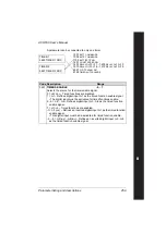
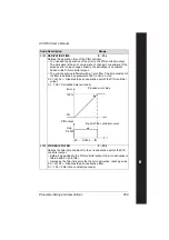
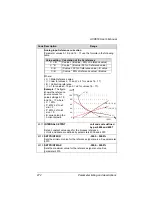
4009
100% VALUE
unit and scale defined
by par. 4006 and 4007
Defines (together with the previous parameter) the scaling applied to
the actual values of the PID controller.
• Units and scale are defined by parameters 4006 and 4007.
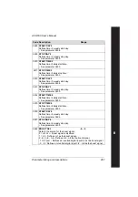
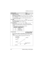
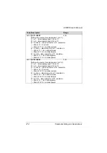
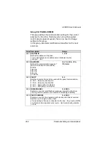
4010
SET POINT SEL
0…19
Defines the reference signal source for the PID controller.
• Parameter has no significance when the PID regulator is by-passed
(see 8121
REG
BYPASS
CTRL
).
0 =
KEYPAD
– Control panel provides reference.
1 =
AI
1 – Analog input 1 provides reference.
2 =
AI
2 – Analog input 2 provides reference.
8 =
COMM
– Fieldbus provides reference.
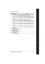
9 =
COMM
+
AI
1 – Defines a fieldbus and analog input 1 (
AI
1)
combination as the reference source. See
on page
.
10 =
COMM
*
AI
1 – Defines a fieldbus and analog input 1 (
AI
1)
combination as the reference source. See
on page
.
11 =
DI
3
U
, 4
D
(
RNC
) – Digital inputs, acting as a motor potentiometer
control, provide reference.
•
DI
3 increases the speed (the U stands for “up”)
•
DI
4 decreases the reference (the D stands for “down”).
• Parameter 2205
ACCELER
TIME
2 controls the reference signal’s rate
of change.
•
R
= Stop command resets the reference to zero.
•
NC
= Reference value is not copied.
12 =
DI
3
U
, 4
D
(
NC
) – Same as
DI
3
U
, 4
D
(
RNC
) above, except:
• Stop command does not reset reference to zero. At restart the motor
ramps up, at the selected acceleration rate, to the stored reference.
13 =
DI
5
U
, 6
D
(
NC
) – Same as
DI
3
U
, 4
D
(
NC
) above, except:
• Uses digital inputs
DI
5 and
DI
6.
14 =
AI
1 +
AI
2 – Defines an analog input 1 (
AI
1) and analog input 2 (
AI
2)
combination as the reference source. See
on page
.
15 =
AI
1 *
AI
2 – Defines an analog input 1 (
AI
1) and analog input 2 (
AI
2)
combination as the reference source. See
on page
.
16 =
AI
1 -
AI
2 – Defines an analog input 1 (
AI
1) and analog input 2 (
AI
2)
combination as the reference source. See
on page
.
17 =
AI
1/
AI
2 – Defines an analog input 1 (
AI
1) and analog input 2 (
AI
2)
combination as the reference source. See
on page
.
19 =
INTERNAL
– A constant value set using parameter 4011 provides
reference.
Code Description
Range
Summary of Contents for ACH550-01
Page 1: ...ACH550 User s Manual ACH550 01 Drives 0 75 110 kW ACH550 UH Drives 1 150 HP ABB ...
Page 10: ...Update Notice 8 ...
Page 12: ......
Page 18: ...6 ACH550 User s Manual ...
Page 50: ...38 Preparing for installation ACH550 User s Manual ...
Page 325: ...313 ACH550 User s Manual ...
Page 358: ...346 ACH550 User s Manual ...
Page 409: ...Technical data 397 ACH550 User s Manual Frame size R1 IP54 UL Type 12 ...
Page 410: ...398 Technical data ACH550 User s Manual Frame size R2 IP54 UL Type 12 ...
Page 411: ...Technical data 399 ACH550 User s Manual Frame size R3 IP54 UL Type 12 ...
Page 412: ...400 Technical data ACH550 User s Manual Frame size R4 IP54 UL Type 12 ...
Page 413: ...Technical data 401 ACH550 User s Manual Frame size R5 IP54 UL Type 12 ...
Page 414: ...402 Technical data ACH550 User s Manual Frame size R6 IP54 UL Type 12 ...
Page 415: ...Technical data 403 ACH550 User s Manual Frame size R1 IP21 UL Type 1 ...
Page 416: ...404 Technical data ACH550 User s Manual Frame size R2 IP21 UL Type 1 ...
Page 417: ...Technical data 405 ACH550 User s Manual Frame size R3 IP21 UL Type 1 ...
Page 418: ...406 Technical data ACH550 User s Manual Frame size R4 IP21 UL Type 1 ...
Page 419: ...Technical data 407 ACH550 User s Manual Frame size R5 IP21 UL Type 1 ...
Page 420: ...408 Technical data ACH550 User s Manual Frame size R6 IP21 UL Type 1 ...
Page 453: ......


