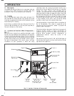


6
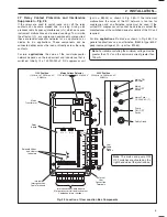
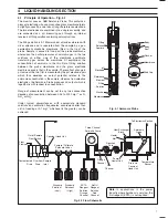
Output
Module 1
Link for the Current
Output required
Output Module 2
(if fitted)
Temperature Input
Module
Input
Module
Protection
Plate
Captive
Screws
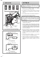
0 to 1mA
0 to 10mA
0 to 20mA
4 to 20mA
1
8
1
8
1
8 1
8
R
C
Load
L
N
External a.c. supply
Relay Contacts
NC C NO
A – a.c. Applications
Load
+
–
External d.c. supply
Relay Contacts
B – d.c. Applications
NC C NO
Diode
…2
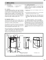
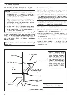
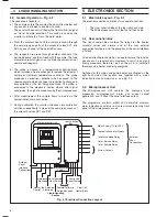
INSTALLATION
3
SETTING UP
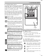
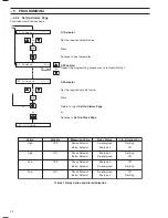
Fig. 2.4 Selecting The Current Output Range
Fig. 2.5 Relay Contact Protection
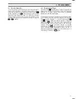
Note.
Before proceeding any further, ensure that all
switches are set to OFF on the right hand side of the
electronics unit – see Fig. 2.3.
a) Ensure that all external electrical and plumbing
connections have been made correctly.
b) Fill reagent and standard solution bottles and connect
them to the monitor. (See Section 8.1 for details of these
solutions.)
c) Fit the probe according to the instructions in Section 8.2.7.
d) Connect the electrical supply and switch on.
Note.
The temperature controlled block requires up to half
an hour to reach the normal control temperature. During
this time, 'Temp. Control Error' is indicated on the display.
Any calibrations are prevented by the microprocessor
during this time.
e) Verify that there is an adequate supply of sample to the
monitor constant head unit.
f)
Fit the pump platen on the peristaltic pumps (see Section
8.2.8) and switch the pumps on with the switch on the side
of the monitor. Ensure that the peristaltic pumps rotate,
and check that sample and reagents are being drawn into
the monitor by observing the progress of any small bubbles
present in the inlet tubes.
g) Run the monitor for at least one hour to allow the
temperature to stabilize, solutions to be pumped into the
system and to purge the air from the pipework. Check for
any leaks around the pipe connections and rectify as
necessary.
h) If the monitor exhibits good stability, i.e.
±
2% of reading,
carry out a calibration – see Programming Page.
i)
Check the condition of the sample filter and replace it if
necessary. Ensure that new filters are fitted correctly by
taking note of the flow directions indicated on the filter
bodies.


