4
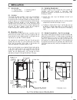
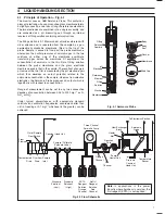
Sample Inlet Pipe
(6 mm i.d.)
Drain Tundish
Contaminated Drain pipe
(9 mm i.d.)
Tube wall fixing clips
N.B.
Sample, drain and overflow pipework
in flexible silicone rubber or PVC
150 mm
(approx)
Monitor Case
Case Hinge Line
Push-on hose connectors
Constant-head unit
250 mm (approximate) length
tubing to allow the case
to open through 90
°
Overflow
Drain
…2
INSTALLATION
Fig. 2.2 Suggested Layout
Note.
It is essential that all
sample pipework to the monitor
is kept as short as possible to
reduce the effects on the
sample due to the presense of
algæ which can build up. This
problem is particularly acute in
the pipework between the filter
and the monitor because of the
small sample flow. Small bore
tubing is essential, e.g. 6 mm
i.d.
2.6
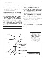
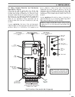
External Electrical Connections – Fig. 2.3
Warning.
• Although certain instruments are fitted with internal fuse
protection, a suitably rated external protection device,
e.g. a 3 A fuse or miniature circuit breaker (m.c.b.),
must also be fitted by the installer.
• Before making any connections, ensure that the power
supply , any high voltage-operated control circuits, high
common mode voltage, including externally powered
alarm circuits, are switched off.
• The power supply earth (ground)
must
be connected to
ensure safety to personnel, reduction of effects of radio
frequency interference (r.f.i.) and correct operation of
the power supply interference filter.
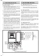
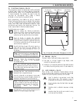
The external electrical connections are to be found in the User
Junction Box with the exception of the optional serial interface
which is connected directly into the Microprocessor Unit. The
cables are passed through the cable glands on the right hand
side of the junction box which are adjacent to the internal
electrical terminals.
Caution.
Slacken the terminal screws fully before making
connections.
The connections are as follows:
a) Mains input 115 V or 240 V. The mains voltage is selected
by means of the voltage selector – see Fig. 2.3.
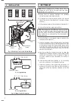
b) Current outputs 1 and 2 – two independent current outputs
for external recording or control. One output is supplied as
standard, the second is supplied as an optional extra – see
Fig. 2.4 for details of current output range.
Information.
Because the current output is isolated, the
negative terminal
must
be connected to earth (ground) if
connecting to the isolated input of another device.
c) Relay 1 and 2 – two concentration alarms.
d) Relay 3 – calibration mode indication. This indicates when
the instrument is off line during a calibration.
e) Relay 4 – instrument 'OUT OF SERVICE' indication. This
indicates that the monitor readings are suspect and it is in
need of attention.
f)
Relay 5 – 'OUT OF SAMPLE' – indication of loss of sample.
g) Optional serial interface – connected into the
Microprocessor Unit. See supplementary instruction
manual for details.

