


40
3
2
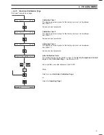
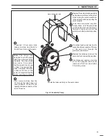
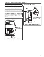
Locate and change the EPROM IC1 – see Fig. A.4.
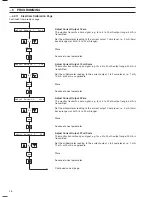
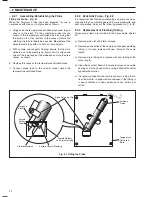
Remove the four screws attaching the PCB to
the assembly.
Note that there are washers between the PCB
cover and the PCB.
Withdraw the PCB and turn it over to
reveal the component side.
1
2
3
Extract IC1 using an approved tool
– see
Caution
in Section A.1.
Fit the replacement IC
– press home firmly.
See Section A.5 for
reassembly instructions.
IC1
IC11
IC3
IC2
IC5
IC4
BA
T1
1
…APPENDIX A
Fig. A.3 Procedure to Remove the PCB
Fig. A.4 Replacing the Software EPROM
A.3
Removing the PCB – Fig. A.3
A.4
Changing the EPROM – Fig. A.4
A.5
Completing the Procedure
1) Fit the PCB using the reverse procedure in
Fig. A.3.
Important Note.
Ensure that the washers
are fitted between the PCB cover and the
PCB.
2) Close the microprocessor section using the
reverse procedure in Fig. A.2.
3) Close and lock the hinged cover – Fig. A.1.
4) The monitor may now be put into service.
5) Check program parameters – see Section 6.
6) Carry out a routine 2-point calibration.


