background image


GER 


29 


6.8  Licht und Lichtszenen 


Durch die individuelle und flexible Belegung der Touch-Bedienflächen lassen sich alle, in die 
EIB- oder Powernetanlage eingebundenen elektrischen Geräte, insbesondere Leuchten, 
schalten. Die jeweiligen Schaltzustände werden im Display entweder im Klartext oder in 
Form von Symbolen (z.B. in Form einer Glühlampe) visualisiert. 


6.8.1 Licht 

steuern 


• 

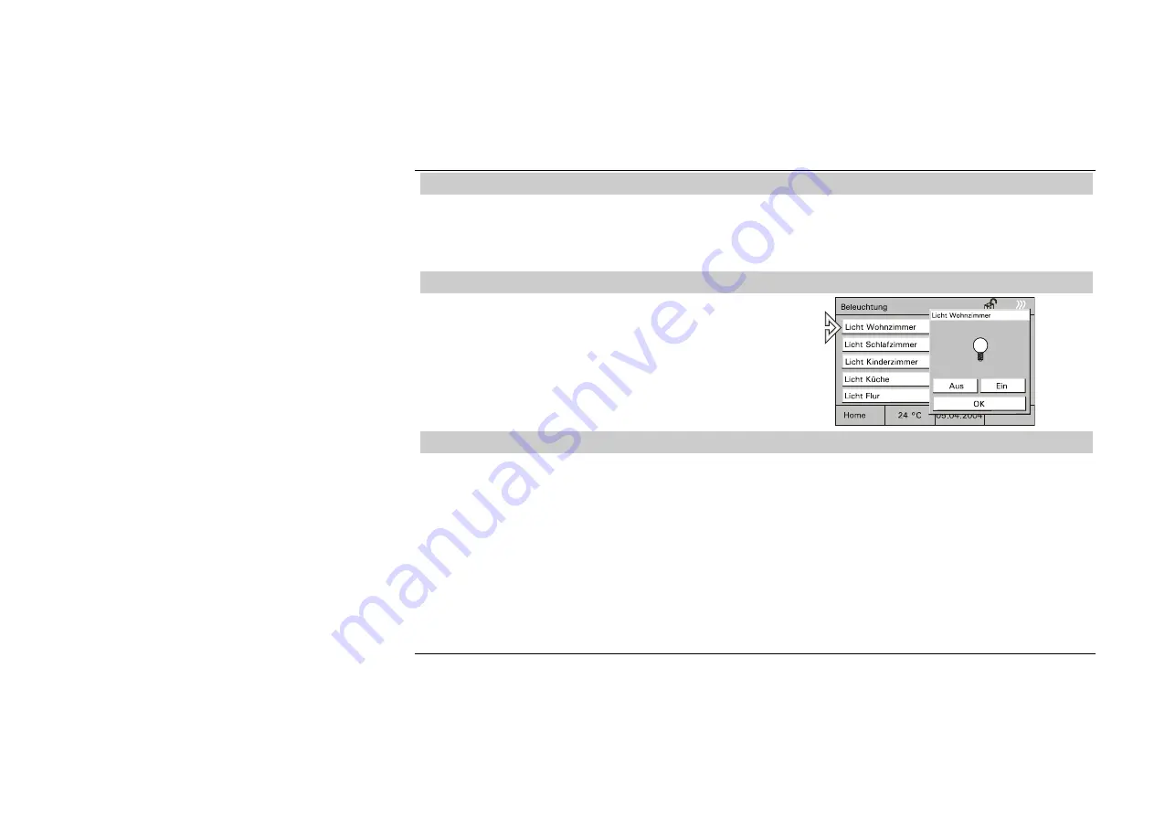
Zum Steuern des Lichts wählen Sie auf der 

Startseite z.B. die Schaltfläche eines 
Raums und dann die Schaltfläche für die 
Beleuchtung. 

• 

Schalten Sie hier das Licht an oder aus. 


Fig. 
48 


6.8.2 Lichtszenen 

abrufen/ändern 


Über Lichtszenen können z.B. individuelle Lichtstimmungen aufgerufen werden, d.h. 
innerhalb eines Raumes werden automatisch verschiedene Leuchten auf unterschiedliche 

Helligkeitswerte eingestellt. Parallel dazu wird z.B. die Jalousie oder Leinwand 
heruntergefahren. So lassen sich für die verschiedensten Situationen wie z.B. Lesen, 
Fernsehen oder auch Präsentationen und Vorführungen individuelle 
Beleuchtungssituationen auf einfache Weise realisieren. 
Innerhalb einer Szene können alle Einstellungen angepasst und neu gespeichert werden. 
Es können in einem Projekt bis zu 32 Lichtszenen realisiert werden wobei jeweils bis zu 6 
(Raumpanel) bzw. 20 (Controlpanel) EIB-Geräte angesteuert werden können. 


Summary of Contents for 6136/100C-500

Page 1: ...4 Status 04 04 Version 04 04 Versie 04 04 Estado 04 04 Stan 04 04 Редакция от 04 04 FRA Mode d emploi dans votre langue v page 5 DUT Bedieningshandleiding zie pagina 5 SPA Manual de Instrucciones en español disponible en la página 5 POL Instrukcja obsługi w języku polskim znajduje się na stronie 5 RUS Инструкция по эксплуатации на русском языке находится на странице 5 ...

Page 2: ......

Page 3: ...6 5 1 Integrierter Raumtemperaturregler 19 6 5 2 Externe Raumtemperaturregler 20 6 6 Zeitprogramme 21 6 6 1 Zeitprogramme aufrufen bearbeiten 22 6 6 2 Schaltzeiten bearbeiten 23 6 6 3 Astrofunktion 24 6 6 4 Einstellen PIN Code 26 6 7 Urlaub und Anwesenheitssimulation 27 6 8 Licht und Lichtszenen 29 6 8 1 Licht steuern 29 6 8 2 Lichtszenen abrufen ändern 29 6 9 Jalousien Rollladen steuern 31 6 10 A...

Page 4: ...schalten der Verbraucher 40 8 Installation 41 8 1 Elektrische Installation 41 8 2 Montage Raum Controlpanel 42 9 Software 43 9 1 Installation 43 9 2 Programmierung 44 10 Gewährleistung 46 10 1 Umfang der Erklärung 46 10 2 Ansprüche des Endverbrauchers aus der Erklärung 46 10 3 Geltungsdauer der Erklärung Anspruchsfrist 47 10 4 Geltungsbereich 47 10 5 Geltendmachung der Ansprüche aus dieser Erkläru...

Page 5: ...lsüblichem Glasreiniger FRA Informations d emploi dans votre langue vous trouvez dans votre banque de données de produits CD Rom ou dans l internet sous www abb de DUT Gebruikersinformatie in het Nederlands vindt u op uw actuele productdatabank CD rom of om te downloaden op www abb com SPA Manual de Instrucciones en español disponible en el CD ROM actual o bien descargándolo en la dirección de Int...

Page 6: ...z Leistungsaufnahme 20VA Betriebstemperatur 0 C bis 45 C Lagerung 20 C bis 60 C Anschluss an Bus TP Busklemmblock Raumtemperaturregler Messbereich 0 C bis 40 C Maße inkl Rahmen B x H x T 218mm x 185mm x 67mm UP Montagedose Maße B x H x T 200mm x 164mm x 60mm ...

Page 7: ...GER 7 4 Geräteansicht 1 Display 320 x 240 Bildpunkte 2 Bedienstift 3 MMC SD Kartenleser Fig 1 ...

Page 8: ...programme 5 Kanäle mit je 5 Schaltzeiten 20 Kanäle mit je 10 Schaltzeiten 20 Kanäle mit je 10 Schaltzeiten Anzahl der Alarm Störmeldungen 5 10 10 IR Kanäle 16 16 16 Anwesenheitssimulation ja ja ja Integrierter Raumtemperaturregler ja ja ja Display 320 x 240 Bildpunkte Graustufen Graustufen 256 Farben Meldefunktion nein ja ja Info Funktion nein ja ja Wecker Timer Funktion nein ja ja Kartenleser SD ...

Page 9: ...gelieferten Stift oder einen Finger Fig 2 6 2 Grundlagen Die Funktionalität des Raum Controlpanels ist software abhängig und richtet sich nach dem gespeicherten Projekt Damit variiert auch das Erscheinungsbild der Bedienseiten Der grundsätzliche Aufbau bleibt jedoch stets gleich Der Hauptseite Projekt Startseite Fig 3 ist eine Unterebene mit Bedienseiten zugeordnet die in zwei Bildschirmansichten ...

Page 10: ...en wechseln Fig 4 Fig 5 In den Raumpaneln 6136 xx können der Grundseite 6 und in den Controlpaneln 6136 xx bis zu 10 Bedienseiten zugeordnet werden Alle Seiten können individuell an das Projekt angepasst werden Ein sinnvoller Seitenaufbau kann z b raumorientiert sein Fig 6 oder funktionsorientiert Fig 7 Fig 6 Fig 7 ...

Page 11: ...GER 11 Die Bedienseiten sind dabei stets wie folgt aufgebaut Startseite Fig 8 Bedienseite Fig 9 Bediendialog Anzeige von Zuständen Fig 10 Fig 8 Fig 9 Fig 10 ...

Page 12: ... der Startseite links oben im Display Rechts oben im Display stellt sich das Symbol Schloss geschlossen dar Das Display ist jetzt gesichert und kann nicht mehr bedient werden Erst erneutes langes Drücken aktiviert das Display wieder Fig 11 Die Sicherung empfiehlt sich immer dann wenn das Gerät in Bereichen mit wechselndem Publikumsverkehr installiert ist oder als Kindersicherung ...

Page 13: ...ugriff auf die Systemeinstellungen kann über einen PIN Code gesichert oder vollständig gesperrt werden Sind die Systemeinstellungen gesperrt können sie vom Anwender nicht geöffnet oder verändert werden Wenden Sie sich in diesem Fall an Ihren Installateur Geben Sie ggf ihren PIN Code ein Fig 12 Datum Stellen Sie mit den Pfeiltasten das korrekte Datum ein Bestätigen Sie die Eingabe mit OK Fig 13 ...

Page 14: ...Eingabe mit OK Fig 14 Displaybe leuchtung Zur Energieeinsparung schaltet sich die Displaybeleuchtung automatisch aus wenn keine Bedienung erfolgt Wählen Sie die gewünschte Abschaltzeit aus der Liste oder deaktivieren Sie die automatische Abschaltung Bestätigen Sie die Eingabe mit OK Fig 15 ...

Page 15: ...r oder die Pfeiltasten ein Bestätigen Sie die Eingabe mit OK Fig 16 Kontrast Helligkeit Stellen Sie die Bildschirmhelligkeit und den Kontrast über die Schieberegler ein Bestätigen Sie die Eingabe mit OK Fig 17 Signaltöne Die Signaltöne unterteilten sich in weitere Unterkategorien Alarmmeldungen Timer Wecker Falsche Eingabe Tastenklick Fig 18 ...

Page 16: ... Bestätigen Sie die Eingabe mit OK Fig 19 Timer Wecker Den Ton für den Timer Wecker können Sie aus der Liste auswählen Sie können den ausgewählten Ton ggf noch testen Bestätigen Sie die Eingabe mit OK Fig 20 Falsche Eingabe Den Kontrollton für falsche Eingaben können Sie ein oder ausschalten Bestätigen Sie die Eingabe mit OK Fig 21 ...

Page 17: ...sschalten Bestätigen Sie die Eingabe mit OK Fig 22 Touch abgleich Ein Abgleich des Touch Displays ist normalerweise nicht erforderlich Sollten Sie trotzdem öfter daneben liegen führen Sie einen Touchabgleich aus Fig 23 Tippen Sie dazu mit dem Stift exakt in die eingeblendeten Zielflächen Fig 24 ...

Page 18: ...ende Klima und die gewünschte Temperatur Die Solltemperatur des Raumes oder auch die Betriebsart des Reglers kann vom Anwender jederzeit verändert werden So kann z B die Nachtabsenkung eingeschaltet werden d h die Raumtemperatur wird über Nacht automatisch heruntergefahren Über das Gerät können auch Raumtemperaturregler in anderen Räumen bzw im ganzen Gebäude beeinflusst werden z B zentrale Nachta...

Page 19: ...egrierten Raumtemperaturreglers RTR abzurufen und ggf anzupassen Der aktuelle Betrieb des RTR Heizen Kühlen wird als Symbol auf der Grundseite angezeigt Fig 26 RTR Betriebs arten 1 Stand by Die Komforttemperatur wird leicht abgesenkt 2 Komfort Die eingestellte Raumtemperatur wird permanent gehalten 3 Nachtabsenkung Absenkung der Raumtemperatur Fig 27 ...

Page 20: ...Externe Raumtemperaturregler Wählen Sie auf einer Bedienseite die Schaltfläche Heizung oder eine entsprechende Schaltfläche Die Bedienseite mit den verfügbaren RTRs wird geöffnet Fig 29 RTR Betriebs arten 1 Stand by Die Raumtemperatur wird leicht abgesenkt 2 Komfort Die eingestellte Raumtemperatur wird permanent gehalten 3 Nachtabsenkung Absenkung der Raumtemperatur Fig 30 ...

Page 21: ...rbraucher z B eine Leuchte EIN oder AUS geschaltet werden nach Wunsch an bestimmten Tagen täglich oder nur am Wochenende Maximal können 20 elektrische Geräte der EIB PN Anlage jeweils zu 5 Raumpanel bzw 10 Controlpanel unterschiedlichen Zeiten geschaltet werden Bis zu 200 Zeitfunktionen sind so möglich Es ist möglich den Zugriff auf die Zeitprogramme vollständig zu sperren oder über einen PIN Code...

Page 22: ...amme wählen Sie die Schaltfläche mit der Datums Zeitanzeige Die möglichen Zeitprogramme werden angezeigt Fig 32 Wählen Sie das gewünschte Zeitprogramm aus Die möglichen Schaltzeiten werden angezeigt Fig 33 Wählen Sie eine Schaltzeit aus Die programmierten Parameter werden angezeigt Fig 34 ...

Page 23: ...GER 23 6 6 2 Schaltzeiten bearbeiten Einstellen des Wochentags Einstellen der Schaltzeit Fig 35 Fig 36 Einstellen des Schaltzustands Einstellen der Schaltfunktion siehe Kap 6 7 Fig 37 Fig 38 ...

Page 24: ...n im Sommer früher auf als im Winter Wählen Sie zum Aktivieren der Astrofunktion die Schaltfläche Astrofunktion Die Astrofunktion wird angezeigt Fig 39 Aktivieren Sie die Astrofunktion Fig 40 Einschränken der Astro Vorgaben aktivieren Wählen Sie im ersten Schritt die Schaltfläche Sperrung und aktivieren Sie die gewünschte Auswahl Fig 41 ...

Page 25: ...Wählen Sie im zweiten Schritt die Schaltfläche Sperrzeit und geben die gewünschte Zeit ein Für die Eingabe weiterer Zeiten wechseln Sie zurück zu den Schaltzeiten und wählen dort die nächste Schaltzeit Fig 42 ...

Page 26: ...eiche können sein 1 Systemeinstellungen ändern 2 Zeitprogramme bearbeiten 3 Meldeanlage scharf schalten Zum Ändern der PIN wählen Sie die Seite Meldeanlage und öffnen das Menü Pin Code ändern Drücken Sie hier die Schaltfläche Ändern Danach werden Sie aufgefordert die aktuelle PIN einzugeben Geben Sie den aktuellen PIN Code ein Bestätigen Sie Ihre Eingabe mit OK und geben den neuen PIN Code ein Bes...

Page 27: ... die Urlaubsfunktion in den Zeitprogrammen eingestellt werden siehe Kapitel 6 6 2 Verfahren Sie zunächst wie in Kapitel 6 6 1 beschrieben Aktivieren Sie die Schaltfunktionen wie gewünscht Fig 44 Anzeigen von Zeitprogrammen s Kapitel Zeitprogramme aufrufen bearbeiten Zum Aktivieren der Urlaubsfunktion wählen Sie die Seite Extras und wechseln hier auf die zweite Seite Geben Sie die Daten für Ihren U...

Page 28: ...s automatisch ein oder ausgeschaltet oder die Jalousie wird geöffnet bzw geschlossen Die Anwesenheitssimulation zeichnet jeden Tag die Schaltzustände von bis zu 10 Geräten auf und speichert sie z B Einschalten der Deckenbeleuchtung im Wohnzimmer am Montag um 20 Uhr Alle Schaltzustände einer Woche werden zwischengespeichert Zum Aktivieren der Anwesenheitssimulation wählen Sie die entsprechende Bedi...

Page 29: ...oder aus Fig 48 6 8 2 Lichtszenen abrufen ändern Über Lichtszenen können z B individuelle Lichtstimmungen aufgerufen werden d h innerhalb eines Raumes werden automatisch verschiedene Leuchten auf unterschiedliche Helligkeitswerte eingestellt Parallel dazu wird z B die Jalousie oder Leinwand heruntergefahren So lassen sich für die verschiedensten Situationen wie z B Lesen Fernsehen oder auch Präsen...

Page 30: ...Sie hier die Lichtszene mit der entsprechenden Schaltfläche Fig 49 Lichtszenen ändern und speichern Starten Sie die gewünschte Lichtszene Stellen Sie nun die Verbraucher so ein dass die Beleuchtung Ihren Vorstellungen entspricht Fig 50 Sie speichern die Einstellungen durch eine lange Berührung ca 4 s der entsprechenden Schaltfläche Die Schaltfläche zeigt als Rückmeldung Speichern Fig 51 ...

Page 31: ...Zum Steuern der Rollade wählen Sie auf der Startseite z B die Schaltfläche Rollladen und dann die entsprechende Schaltfläche Bewegen Sie mit den Pfeiltasten die Jalousien Rollladen auf oder ab Kurz tippen Stopp Lamellen verstellen Lang tippen Auf oder Abfahren Fig 52 Steuern über Zeit programme Rollladen steuern über Zeitprogramme siehe Kapitel Zeitprogramme aufrufen bearbeiten ...

Page 32: ...xt angezeigt wird Fig 53 Die angezeigten Meldungen bleiben solange im Vordergrund bis sie durch den Anwender quittiert werden Dies gilt auch wenn die Alarm oder Störungsursache zwischenzeitlich beseitigt wurde und der Normalzustand wieder eingetreten ist Dadurch ist gewährleistet dass ein aufgetretener Alarm oder eine aufgetretene Störung nicht unbemerkt bleibt Dass eine Stör Alarmmeldung vorliegt...

Page 33: ...internen Alarm auslöst Zusätzlich kann z B eine externe Hupe oder Sirene eingeschaltet werden Parallel wird die Meldung im Display angezeigt siehe auch Alarm Störmeldungen Bei Bedarf kann eine Meldung auch an eine Telefonschnittstelle übermittelt werden die Sie oder weitere Hilfe per Telefon alarmiert Hat ein Fensterkontakt oder ein Bewegungsmelder eine Störung wird dies durch entsprechende Störme...

Page 34: ... Unscharfschaltung Der Betriebszustand der Meldeanlage wird durch ein Symbol angezeigt Fig 55 Nach der Auswahl Scharf oder Unscharf werden Sie aufgefordert den PIN Code einzugeben Fig 56 Nach der Bestätigung der Eingabe mit der Schaltfläche OK wird die Meldezentrale entsprechend geschaltet Fig 57 Der PIN Code kann nur bei unscharfer Meldezentrale geändert werden ...

Page 35: ...ndet Jede Nachricht bleibt solange im Vordergrund bis sie mit OK bestätigt oder mit Löschen gelöscht wird Das Vorliegen einer Information wird durch ein Symbol angezeigt Zum Erstellen einer Information wählen Sie die Seite Extras und dann die Schaltfläche Infoseite Die Infoseite wird angezeigt Fig 58 Schreiben Sie mit dem PDA Stift eine Notiz oder bearbeiten Sie eine gespeicherte Info Fig 59 ...

Page 36: ...t eingestellt In beiden Fällen werden Sie bei Erreichen der eingestellten Zeit mit einem Alarmton darauf aufmerksam gemacht Zum Einstellen der Zeit wählen Sie die Seite Extras und dann die Schaltfläche Timer oder Wecker Nach dem Einstellen der Zeit aktivieren Sie mit der Schaltfläche Start Stop den Timer Wecker Ein aktiver Timer oder Wecker wird mit einem Symbol angezeigt Fig 60 ...

Page 37: ...B Alle Raum und Controlpanels sind mit einem Infrarot Empfänger ausgestattet und über die Handsender 6010 25 und 6010 25 500 fernbedienbar Detaillierte Informationen und Bedienungshinweise finden Sie in der separaten Gebrauchsanweisung zum Handsender Fig 61 ...

Page 38: ...936 100CB Der IR Handsender bietet zur Ansteuerung des Raumpanels folgende Möglichkeiten Light Änderung der Beleuchtung Record Speichern einer Lichtszene 0 9 Anwahl Leuchte 1 bis 10 A Anwahl Lichtszene 1 C Anwahl Lichtszene 2 D Anwahl Lichtszene 3 F Anwahl Lichtszene 4 B Ein oder heller dimmen E Aus oder dunkler dimmen Stop Alles Aus Fig 62 ...

Page 39: ...lten Die Schreibweise LIGHT 1 B in der Tabelle bedeutet dass die drei Tasten nacheinander nicht gleichzeitig betätigt werden müssen Funktion Tastenbetätigung Leuchte 1 EIN LIGHT 1 B Leuchte 1 heller dimmen LIGHT 1 B B dauerhaft betätigen Leuchte 1 AUS LIGHT 1 E Leuchte 1 dunkler dimmen LIGHT 1 E E dauerhaft betätigen Bedienung Leuchten 2 9 analog zu Leuchte 1 Leuchte 10 EIN LIGHT 0 B Leuchte 10 he...

Page 40: ... Die Schreibweise LIGHT A in der Tabelle bedeutet dass die zwei Tasten nacheinander nicht gleichzeitig betätigt werden müssen Funktion Tastenbetätigung Aufruf Lichtszene 1 LIGHT A Aufruf Lichtszene 2 LIGHT C Aufruf Lichtszene 3 LIGHT D Aufruf Lichtszene 4 LIGHT F Speichern Lichtszene 1 LIGHT RECORD A Speichern Lichtszene 2 LIGHT RECORD C Speichern Lichtszene 3 LIGHT RECORD D Speichern Lichtszene 4...

Page 41: ...lation 8 1 Elektrische Installation Geräteanschluss ABB i Bus Geräteanschluss ABB Powernet Fig 63 Fig 64 Keine spannungsführenden Leitungen hinter dem Gerät durch die UP Dose führen Trennung von TP Bus und Netzleitung ...

Page 42: ...ie UP Dose 6136 UP 1 Klemmen an den Leitungen 230V ggf TP anbringen siehe Kapitel Anschluss 2 Klemmen an das Gerät anschließen 3 Gerät in UP Montagedose einsetzen und festschrauben Fig 64 Fig 65 4 Rahmen einhängen und mit beiliegender Schraube sichern Fig 65 Fig 66 ...

Page 43: ...duktdatenbank in die ETS importieren 3 Gerät parametrieren konfigurieren Power Projekt 4 x 1 Panel Inbetriebnahmesoftware aus der aktuellen EIB Datenbank oder von der Power Projekt CD installieren 2 Gerät parametrieren konfigurieren siehe oben Die EIB Datenbank können Sie über ABB direkt beziehen oder im Internet unter www abb com downloaden ...

Page 44: ...nach Konfiguration mehrere Stunden dauern Programmieren Sie das Gerät nur bei kleineren Projektänderungen über den Bus Empfehlung Programmierung mit einer SD MMC Karte vornehmen Program mierung über SD MMC Karte 1 Legen Sie das neue Projekt mit der Inbetriebnahmesoftware auf einem PC an und speichern Sie das Projekt auf einer SD MMC Karte 2 SD Karte in das Raum Controlpanel einführen und Button Mu...

Page 45: ...mmiermodus wird automatisch verlassen die Grundansicht wird angezeigt Fig 69 Program mierung über den Bus 1 Legen Sie das neue Projekt auf einem PC an 2 Verbinden Sie den Computer über eine RS 232 oder USB Schnittstelle mit dem Bus 3 Button EIB Programmiermodus drücken und in der Auswahl aktiv setzen Fig 70 4 Programmierung vom PC starten Dieser Vorgang kann mehrere Stunden dauern ...

Page 46: ...Mangel Sie gilt insbesondere nicht wenn die Beeinträchtigung der Brauchbarkeit des Gerätes auf natürliche Abnutzung unsachgemäßer Verwendung einschließlich Einbau oder Einwirkung von aussen beruht Diese Erklärung stellt keine Beschaffenheitsgarantie im Sinne der 443 und 444 BGB dar 10 2 Ansprüche des Endverbrauchers aus der Erklärung Im Falle eines berechtigten und ordnungsgemäß geltend gemachten ...

Page 47: ...and sitzenden Händlern 10 5 Geltendmachung der Ansprüche aus dieser Erklärung Zur Geltendmachung der Ansprüche aus dieser Erklärung ist das Gerät zusammen mit der ausgefüllten Servicekarte und einer Kopie des Kaufbeleges sowie einer kurzen Erläuterung des beanstandeten Mangels unverzüglich an den zuständigen Fachhändler bei dem das Gerät bezogen wurde oder das ABB Service Center auf Kosten und Gef...

Page 48: ......

Page 49: ...0073 1 6490 Rev 1 0073 1 6490 Raumpanel 6136 30M 500 Controlpanel 6136 100M 500 Controlpanel 6136 100C 500 Status 04 04 ENG Operating Instructions ...

Page 50: ......

Page 51: ...grated room thermostat 19 6 5 2 External room thermostats 20 6 6 Time programmes 21 6 6 1 Calling up modifying time programmes 22 6 6 2 Modifying switching times 23 6 6 3 Astro function 24 6 6 4 Setting of PIN code 26 6 7 Holiday and presence simulation 27 6 8 Lights and light scenes 29 6 8 1 Controlling light 29 6 8 2 Calling up modifying light scenes 29 6 9 Controlling blinds roller blinds 31 6 ...

Page 52: ...7 2 3 Switching off the consumers 40 8 Installation 41 8 1 Electric installation 41 8 2 Installation of room control panel 42 9 Software 43 9 1 Installation 43 9 2 Programming 44 10 Warranty 46 10 1 Scope of representation 46 10 2 End user s claims from the representation 46 10 3 Period of validity of representation claim period 47 10 4 Area of validity 47 10 5 Assertion of claims from this repres...

Page 53: ...and or disassembly A scratched screen surface will affect monitor handling Never use any hard or sharp pointed objects for entries on the touch screen monitor The screen surface may be damaged by such objects Do not spray any detergents directly on the screen surface Clean the screen using a soft cloth and commercially available glass cleaner ...

Page 54: ...umption 20VA Operating temperature 0 C to 45 C Storage 20 C to 60 C Bus connection TP Bus terminal block Room thermostat measuring range 0 C to 40 C Dimensions incl frame W x H x D 218 mm x 185 mm x 67 mm Flush mounting box Dimensions W x H x D 200 mm x 164 mm x 60 mm ...

Page 55: ...ENG 7 4 Unit view 1 Display 320 x 240 pixels 2 Pen 3 MMC SD card reader Fig 1 ...

Page 56: ... channels with 5 switching times each 20 channels with 10 switching times each 20 channels with 10 switching times each Number of alarm fault messages 5 10 10 IR channels 16 16 16 Presence simulation yes yes yes Integrated room thermostat yes yes yes Display 320 x 240 pixels Grey levels Grey levels 256 colours Message function no yes yes Info function no yes yes Alarm clock timer function no yes y...

Page 57: ...plied pen or a finger to do this Fig 2 6 2 Fundamentals The functions of the room control panel are software dependent and are determined by the saved project Thus the appearance of the operating pages varies as well However the basic structure is always the same The main page Project start page Fig 3 has a sub level with operating pages which can be displayed in two screen views Fig 3 ...

Page 58: ...g 4 Fig 5 On the room panels 6136 xx 6 operating pages can be allocated to the main page and up to 10 operating pages in the control panels 6136 xx All pages can be individually adapted to the project A reasonalbe page structure may e g be room oriented Fig 6 or function oriented Fig 7 Fig 6 Fig 7 ...

Page 59: ...ENG 11 The operating pages are always structured as follows Start page Fig 8 Operating page Fig 9 Operator dialogue status display Fig 10 Fig 8 Fig 9 Fig 10 ...

Page 60: ... left in the display for more than 3 seconds At the top right of the display the Lock symbol appears being closed The display is now safeguarded and cannot be operated any more The display is only enabled by pressing long again Fig 11 Safeguarding the display is recommended whenever the unit is installed in areas where many people come and go or as a child lock ...

Page 61: ...a new project Access to the system settings can be safeguarded by a PIN code or completely blocked When the system settings are blocked they cannot be accessed or modified by the user In this case please contact your electrician Enter your PIN code if available Fig 12 Date Set the correct date using the arrow keys Confirm your entry with OK Fig 13 ...

Page 62: ...entry with OK Fig 14 Display lighting To save energy the display lighting switches itself off automatically when the unit is not actuated Select the desired Lighting Off time from the list or disable the automatic Lighting Off function Confirm your entry with OK Fig 15 ...

Page 63: ...ider or the arrow keys Confirm your entry with OK Fig 16 Contrast Brightness Set the screen brightness and the contrast using the sliders Confirm your entry with OK Fig 17 Warning tones The warning tones are subdivided into further sub categories Alert messages Timer Alarm clock Incorrect input Keypad tones Fig 18 ...

Page 64: ...ou wish Confirm your entry with OK Fig 19 Timer Alarm clock You may select the timer alarm clock tone from the list You may also test the selected tone if you wish Confirm your entry with OK Fig 20 Incorrect input You may enable or disable the signalling tone for incorrect inputs Confirm your entry with OK Fig 21 ...

Page 65: ... Confirm your entry with OK Fig 22 Touch adjustment Adjusting the touch display will usually not be necessary Should you still go wrong frequently with your pen or your finger please adjust the touch display Fig 23 To do this point your pen exactly into the appearing target points Fig 24 ...

Page 66: ...side the room The user may modify the set room temperature and the thermostat operating mode at any time E g a nighttime temperature reduction can be activated i e the room temperature is reduced automatically at night This unit can also control room thermostats in other rooms and or in the entire building e g for realizing a central nighttime temperature reduction feature Please refer to the chap...

Page 67: ...d room thermostat if necessary The current operating mode of the room thermostat heating cooling is shown as a symbol on the main page Fig 26 Room thermostat operating modes 1 Stand by The comfort temperature is slightly reduced 2 Comfort The set room temperature is permanently maintained 3 Nighttime temperature reduction Reduction of room temperature Fig 27 ...

Page 68: ...stats Select the Heating system button on an operating page or another button as required The operating page with the available room thermostats is opened Fig 29 Room thermostat operating modes 1 Stand by The room temperature is slightly reduced 2 Comfort The set room temperature is permanently maintained 3 Nighttime temperature reduction Reduction of room temperature Fig 30 ...

Page 69: ...led automatically using time programmes A consumer e g a lamp can be switched ON or OFF on certain days every day or during the weekend only if desired A maximum of 20 electrical units of the EIB PN system can be controlled at 5 room panel or 10 control panel different times each This allows up to 200 time functions Access to the time programmes can be completely blocked or safeguarded by a PIN co...

Page 70: ...fy the time programmes select the button displaying the date time The possible time programmes are displayed Fig 32 Select the desired time programme The possible switching times are displayed Fig 33 Select a switching time The programmed parameters are displayed Fig 34 ...

Page 71: ...ENG 23 6 6 2 Modifying switching times Setting the weekday Setting the switching time Fig 35 Fig 36 Setting the switching status Setting the switching function see chapter 6 7 Fig 37 Fig 38 ...

Page 72: ...r e g the blinds open earlier during summer than during winter To activate the astro function select the Astro Function button The Astro Function is displayed Fig 39 Enable the astro function Fig 40 Enabling Restriction of Astro settings In the first step select the Closing button and enable your selection Fig 41 ...

Page 73: ...ENG 25 In the second step select the Closing Time button and enter the desired time To enter further times go back to the switching times and select the next switching time there Fig 42 ...

Page 74: ...ted areas may be 1 Modification of system settings 2 Modification of time programmes 3 Activation of message system To modify the PIN select the Message system page and open the Change PIN Code menu Now press the Change button Now you will be requested to enter the current PIN Enter the current PIN code Confirm your entry with OK and enter the new PIN code Confirm your entry with OK Enter the new ...

Page 75: ...utdoor lights the holiday function allows setting this in the time programmes see chapter 6 6 2 First proceed as described in chapter 6 6 1 Enable the switching function as desired Fig 44 For displaying time programmes see chapter Calling up modifying time programmes To enable the holiday function select the Extra page and go to the second page Enter the date of your holiday using the arrow keys F...

Page 76: ... up to 10 units on and off during the day or opening and closing the blinds The presence simulation records the switching statuses of up to 10 units per day and stores them e g switching on of ceiling lighting in the living room at 8 00 p m on Monday All switching statuses of one week are stored To enable the presence simulation select the corresponding operating page Select Presence simulation an...

Page 77: ...re you can switch the light on and off Fig 48 6 8 2 Calling up modifying light scenes Individual light atmospheres can be called up using light scenes i e different lights are automatically set to different brightness values in a given room At the same time e g the blind or a linen is rolled down In this way individual lighting scenes for the most varied situations e g reading watching TV or for p...

Page 78: ...a light scene Start the light scene here using the corresponding button Fig 49 Modifying and saving light scenes Start the desired light scene Now set the electric consumers so that the lighting complies with your wishes Fig 50 Save the setting by touching the corresponding button long approx 4 s The button reads Saving as a feedback Fig 51 ...

Page 79: ... To control the roller blind select e g the button Roller blind on the start page and then the corresponding button Use the arrow keys to move the blinds roller blinds up or down Press briefly to stop and adjust slats Press long to move up or down Fig 52 Control by time programmes For information about roller blind control by time programme see chapter Calling up modifying time programmes ...

Page 80: ...displayed in plain text with date and time Fig 53 The displayed messages remain in the foreground until they are acknowledged by a user This also applies if the reason for the alarm or the fault has meanwhile been removed and the normal condition has been restored This guarantees that an alarm or a fault will not go unnoticed An acoustic signal can indicate that there is a fault alarm see chapter ...

Page 81: ...iggers the internal alarm In addition e g an external horn or a siren can be switched on At the same time the message is displayed in the display see also List of alerts If required a message may also be transferred to a telephone interface which informs you or calls for further help by phone If a window contact of a motion detector is faulty this is indicated by a corresponding fault message see ...

Page 82: ...e Inactivate Alarm System The operating status of the message system is shown by a symbol Fig 55 After selecting Armed or Disarmed you will be requested to enter the PIN code Fig 56 After confirming the entry with the OK button the message centre is activated or inactivated Fig 57 The PIN code can be changed only when the message centre is inactive ...

Page 83: ...ast saved information is shown Each message remains in the foreground until it is confirmed with OK or deleted with Clear A symbol indicates when an information has arrived To write an information select the Extra page and then the Infopage button The info page is displayed Fig 58 Write a note using the PDA pen or edit a saved information Fig 59 ...

Page 84: ...e is set using the Alarm clock function In both cases your attention will be drawn to the expiry of the set time by an alarm sound To set the time select the Extra page and then the Timer or Alarm clock button After setting the time enable the timer alarm clock with the Start Stop button An enabled timer or alarm clock is shown by a symbol Fig 60 ...

Page 85: ...and control panels are equipped with an infrared receiver and may be remote controlled with the hand held transmitters 6010 25 and 6010 25 500 For detailed information and operating information please refer to the separate Instruction Manual of the hand held transmitter Fig 61 ...

Page 86: ...CB The IR hand held transmitter provides the following possibilities for controlling the room panel Light Modification of lighting Record Saving a light scene 0 9 Selection of lamp 1 to 10 A Selection of light scene 1 C Selection of light scene 2 D Selection of light scene 3 F Selection of light scene 4 B On or brighter E Off or darker Stop Everything off Fig 62 ...

Page 87: ... lamps according to the table below LIGHT 1 B in the table means that these three keys must be pressed one after the other not simultaneously Function Keys to be pressed Lamp 1 ON LIGHT 1 B Lamp 1 brighter LIGHT 1 B press B permanently Lamp 1 OFF LIGHT 1 E Lamp 1 darker LIGHT 1 E press E permanently Lamps 2 9 are actuated in the same way as lamp 1 Lamp 10 ON LIGHT 0 B Lamp 10 brighter LIGHT 0 B pr...

Page 88: ... table below LIGHT A in the table means that these two keys must be pressed one after the other not simultaneously Function Keys to be pressed Call up light scene 1 LIGHT A Call up light scene 2 LIGHT C Call up light scene 3 LIGHT D Call up light scene 4 LIGHT F Save light scene 1 LIGHT RECORD A Save light scene 2 LIGHT RECORD C Save light scene 3 LIGHT RECORD D Save light scene 4 LIGHT RECORD F 7...

Page 89: ...nstallation 8 1 Electric installation ABB i bus connection ABB Powernet connection Fig 63 Fig 64 Do not lay energized lines behind the unit through the flush mounting box Separate the TP bus from the mains lines ...

Page 90: ...d in flush mounting box 6136 UP 1 Fit terminals to the lines 230V TP if required see chapter Connection 2 Connect terminals to the unit 3 Insert unit into flush mounting box and tighten screws Fig 64 Fig 65 4 Attach the frame and secure it using the enclosed screw Fig 65 Fig 66 ...

Page 91: ...product database into the ETS 3 Configure the unit and set the parameters Power Projekt 4 x 1 Install the panel commissioning software from the current EIB database or from the Power Projekt CD 2 Configure the unit and set the parameters see above The EIB database can be purchased directly from ABB or downloaded from the Internet at www abb com ...

Page 92: ...may take several hours depending on the configuration Use bus progamming only for minor project changes We recommend programming with an SD MMC card Programmi ng with SD MMC card 1 Create the new project with the commissioning software on a PC and save the project on an SD MMC card 2 Insert the SD card into the room control panel and press the Read Multimedia SD card button Fig 68 Fig 68 ...

Page 93: ... automatically 5 The units exits the programming mode automatically and the basic view is displayed Fig 69 Programmi ng using the bus 1 Create the new project on a PC 2 Connect the computer with the bus via an RS 232 or a USB interface 3 Press the EIB Programming Mode button and enable it Fig 70 4 Start programming from the PC This process may take several hours ...

Page 94: ...ed at the time of handing over to the end user It shall not apply in particular if the impairement of the usefulness of the device is due to natural wear improper use including installation or outside effects This representation shall not constitute a warranty of condition within the meaning of 443 and 444 of the German Civil Code 10 2 End user s claims from the representation In case of a legitim...

Page 95: ...users resident in Germany and or purchases from dealers in Germany 10 5 Assertion of claims from this representation To assert the claims from this representation the device with the completed service card a copy of the purchase voucher and a brief description of the defect must immediately be sent to the competent dealer from whom the device was purchased or to the ABB Service Center at the cost ...

Reviews: