In most applications it is required to connect automatic/general/external emergency
stop switches. It is highly recommended to connect the stop switches as one of
the following figures for the best safety performance. When the 24 V power is
provided by customer instead of 24V_CH1/2, it shall be within the tolerance of 24
V -0%/+10%.
Customer provided power
0V_CH1_CH2
24V_CH1
AS1+ / ES1+
AS1- / ES1-
0V_CH1_CH2
24V_CH2
AS2+ / ES2+
AS2- / ES2-
0V_CH1_CH2
24V_CH1
AS1+ / ES1+
AS1- / ES1-
0V_CH1_CH2
24V_CH2
AS2+ / ES2+
AS2- / ES2-
0V_CH1_CH2
24V_CH1
AS1+ / ES1+
AS1- / ES1-
0V_CH1_CH2
24V_CH2
AS2+ / ES2+
AS2- / ES2-
0V_CH1_CH2
24V_CH1
AS1+ / ES1+
AS1- / ES1-
0V_CH1_CH2
24V_CH2
AS2+ / ES2+
AS2- / ES2-
Customer_24V_CH1
Customer_24V_CH2
Customer_0V_CH1
Customer_0V_CH2
Customer_24V_CH1
Customer_24V_CH2
Customer_0V_CH1
Customer_0V_CH2
(A)
(B)
(C)
(D)
Customer provided power
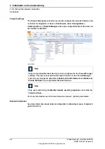
xx1900000600
Note
It is prohibited to connect the dual-channel switch as shown in the following
figure, as this does not comply with the Cat.3 structure.
0V_CH1_CH2
24V_CH1
AS1+ / ES1+
AS1- / ES1-
0V_CH1_CH2
24V_CH2
AS2+ / ES2+
AS2- / ES2-
0V_CH1_CH2
24V_CH1
AS1+ / ES1+
AS1- / ES1-
0V_CH1_CH2
24V_CH2
AS2+ / ES2+
AS2- / ES2-
(A)
(B)
xx1900000599
For more connections other than those illustrated above, carefully assess the risk
before use and contact your local ABB for support.
Continues on next page
Product manual - OmniCore C90XT
97
3HAC073706-001 Revision: E
© Copyright 2020-2021 ABB. All rights reserved.
3 Installation and commissioning
3.5.9 Descriptions for connectors
Continued
Summary of Contents for OmniCore C90XT
Page 1: ...ROBOTICS Product manual OmniCore C90XT ...
Page 36: ...This page is intentionally left blank ...
Page 50: ...This page is intentionally left blank ...
Page 360: ...This page is intentionally left blank ...
Page 420: ...This page is intentionally left blank ...
Page 428: ...This page is intentionally left blank ...
Page 452: ...This page is intentionally left blank ...
Page 456: ......
Page 457: ......


