Publication No. 500-9300527837-000 Rev. A.0
Functional Description 47
5.14 I
2
C Bus
The PCH has a single I
2
C bus, supporting SMBus 2.0.
I
2
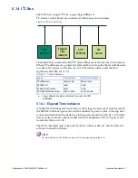
C devices on the board are connected to this bus as shown below:
Figure 5-4 I
2
C Bus Structure
The table below summarizes the I
2
C slave addresses of the devices in the system.
Where I
2
C addresses are quoted, the 8-bit address is the value that would be used
to write to the device on the bus (i.e., the 7-bit device address and the least
significant bit (LSB) set to ‘0’).
5.14.1 Elapsed Time Indicator
A Dallas DS1682 Elapsed Time Indicator (ETI) logs the amount of time for which
the SBC347A has been powered, and the number of power cycles. Powerup time
is only recorded when the platform is fully powered and not in S3, S4, or S5 states.
Power cycle events are only recorded when the backplane VS3 (+5V) power rail
transitions from on to off.
The ETI is intended only to be used by Abaco software drivers. See the relevant
software manual for details.
LINK
For more details on the ETI device, see
http://www.maximintegrated.com
.
Table 5-11 I
2
C Bus Addresses
Device
7-bit Address
8-bit Write Address
PCH (Master)
Master only
Master only
DS1682 ETI
0x6B
0xD6
PCA9560 DIP switch
0x4D
0x9A
SPD EEPROM (onboard)
a
a.
User software should not attempt to access the SPD
EEPROMs.
0x50 to 0x53
0xA0 to 0xA6
PCH
(Master)
SPD
EEPROM
Elapsed
Time
Indicator
DIP
Switch


