Appendix B
Interconnect Drawings
B-3
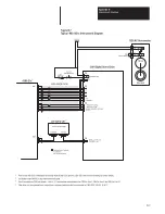
DRAIN
MOTOR
RESOLVER
S1
S3
S2
S4
BLU
YEL
BLK
RED
B2
B1
K2
K1
T1
T2
T3
SHIELD
GND
1326AB–BXX AND 1326AB–AXX
CR
TYPICAL CONTROL CIRCUIT
115V AC, 50/60 HZ.
STOP
CR
LS
START
TB4–17
TB4–18
TB4–13
TB4–14
TB4–12
TB4–11
DRAIN
MOTOR
RESOLVER
R1
C = 6800pf
S1
S3
S2
S4
BLU
YEL
BLK
RED
B2
B1
K2
K1
T1
T2
T3
SHIELD
GND
CONNECT TO DRIVE
GROUND STUD
TO CUSTOMER
FAULT CIRCUIT
BRAKE
(WHEN SUPPLIED)
1326–CPCXX CABLE
1326AB–CXX AND 1326AB–B4X
Y SECONDARY
X SECONDARY
CABINET GROUND BUS
WHT
BLK
BLK
RED
BLK
GRN
BRANCH CIRCUIT
DISCONNECT
NOTE 1
NOTE 6
DROK*
M*
M*
(EMI SHIELD)
B
G
H
I
F
8
3
2
1
6
4
C
D
A
E
5
9
3
2
1
8
7
6
9
5
C
G
H
I
D
E
F
A
B
C
B
A
F
E
D
G
H
I
J
A
B
C
D
E
F
G
H
I
J
* INDICATES COMPONENT LOCATED IN CONTROLLER
RED/WHT
YEL/WHT
R2
RED/WHT
YEL/WHT
TO CUSTOMER
FAULT CIRCUIT
BRAKE
(WHEN SUPPLIED)
1
C.T. NOT REQUIRED – DO NOT
CONNECT TO GROUND
TRANSFORMER
THERMAL
PROTECTION
MOTOR
THERMAL
PROTECTION
NOTE 8
USE 1326–CPABXX CABLE
USE 1326–CFUXX CABLE
R1
C = 6800pf
R2
12 AWG (2.5 mm
2
)
16 AWG (1.0 mm
2
)
1
REQUIRED ONLY WITH IMC 110, 120, 121, AND 123 CONTROLLERS
CR2
Summary of Contents for ALLEN-BRADLEY 1391-DES
Page 1: ...User Manual 1391 DES Digital AC Servo Drive...
Page 9: ...Chapter 1 Introduction 1 10 End of Chapter...
Page 37: ...Chapter 5 Inputs Outputs and Switch Settings 5 8 End of Chapter...
Page 84: ...Chapter 8 Start Up 8 16 End of Chapter...
Page 88: ...Chapter 9 1326 AC Servomotors 9 4 End of Chapter...
Page 106: ...Chapter 11 Troubleshooting 11 12 End of Chapter...
Page 122: ...Appendix B Interconnect Drawings B 12 End of Appendix...
Page 126: ...Appendix C Cable Information C 4 End of Appendix...
Page 134: ...Appendix E Parameter Record E 8 End of Appendix...
Page 135: ...Notes...
Page 136: ...Notes...
Page 137: ...Notes...
Page 138: ...Notes...
Page 139: ...Notes...
Page 140: ...Notes...
Page 141: ...Notes...
Page 142: ...Notes...
Page 143: ...Notes...
Page 144: ...Notes...
Page 147: ...IMC is a trademark of Allen Bradley Company Inc...


