34
Electrical
Verify the unit nameplate agrees with power supply. Connect power and control wiring to the unit
as shown in Figure 19 and in the unit specific wiring diagram, which shows factory and field wiring
and is attached to the inside of the door of the control compartment.
Table 2 - Nameplate Voltage Markings & Tolerances
Hz Nameplate
Voltage
Nominal
System
Voltage
Operating Voltage Range
1
Acceptable Performance
Range
2
Min
Max
Min
Max
60
115
120
104
127
108
126
208/230
208/240
187
254
187
252
208
208
187
228
187
228
230
240
208
254
216
252
265
277
240
293
249
291
460
480
416
508
432
504
575
600
520
635
540
630
50
230
230
198
254
208
254
400
400
344
440
360
440
Notes:
1.
Operating voltage is the min and max voltage for which the unit can function. Never
operate outside of this min and max voltage.
2.
The Acceptable Performance Range is the min and max voltage for which the unit
performance is designed and rated to give acceptable performance.
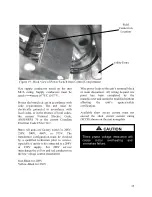
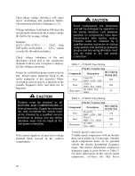
Route power and control wiring, separately,
through the utility entry in the base of the
unit. Do not run power and control signal
wires in the same conduit. The utility entry is
located in the unit base in the front right hand
corner of the unit (compressor compartment).
See unit drawing for specific location.
Figure 18 - Unit Base Utility Entry
Electric shock hazard. Before
attempting to perform any installation,
service, or maintenance, shut off all
electrical power to the unit at the
disconnect switches. Unit may have
multiple power supplies. Failure to
disconnect power could result in
dangerous operation, serious injury,
death, or property damage.
WARNING
Electrical and gas entries into the unit
must be properly sealed. Failure to
seal the entries may result in damage
to the unit and property.
CAUTION
Summary of Contents for RQ NextGen Series
Page 2: ......
Page 26: ...26 Figure 3 RQ Cabinet Standard and Power Exhaust Gasket Locations...
Page 40: ...40 Figure 23 Post Corner Hole Piping Figure 24 Post Back Hole Piping...
Page 88: ...88 Gas Heater Operating Instructions Figure 36 Gas Heater Instructions...
Page 95: ...95...
Page 96: ...96...
Page 105: ...105 Maintenance Log E Coated Coil...
Page 107: ...107...


