


84
for natural gas, or 19.6 mmHg (10.5” w.c.)
for propane..
For two stage gas valves, the low stage
setting shall be set at 2.1 mmHg (1.1” w.c.)
for natural gas, 9.34 mmHg (5.0” w.c.) for
propane. For modulating heaters, the safety
shut-off valve would be set following the
instructions above, then from a provided
pressure tap in the gas train immediately
preceding the burner manifold the
modulating valve is set to maintain a
maximum of 6.5 mmHg (3.5” w.c.) and a
minimum of .75 mmHg (0.4” w.c).
Gas Pressure Regulator & Overpressure
Protection Device
A gas pressure regulator shall be installed if
natural gas supply pressure to the unit is
greater than 19.6 mmHg (10.5” w.c.) and less
than 13.8 kpa (2 psi) (103.5 mmHg [55.4”
w.c.]) and if propane gas supply pressure is
greater than 24.3 mmHg (13” w.c.) and
less than 13.8 kpa (2 psi) (103.5 mmHg
[55.4” w.c.]). Regulators shall comply with
the latest edition of the Standard for Line
Pressure Regulators, ANSI Z21.80/CSA
6.22.
Both a gas pressure regulator and
overpressure protection device (OPD) shall
be installed if gas supply pressure to the unit
is greater than 13.8 kpa (2 psi) (103.5 mmHg
[55.4” w.c.]) and less than 34.5 kpa (5 psi)
(258.57 mmHg [138.4” w.c.]), in compliance
with ANSI Z21.80/CSA 6.22. For proper
heater operation, pressure to the regulator
SHALL NOT be greater than 34.5 kpa (5 psi)
(258.57 mmHg [138.4” w.c.]).
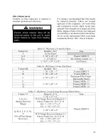
Piping Supports
Gas supply piping shall be supported directly
at the connection to the unit and at intervals
listed in the following table with metal straps,
blocks, or hooks. Piping shall not be strained
or bent.
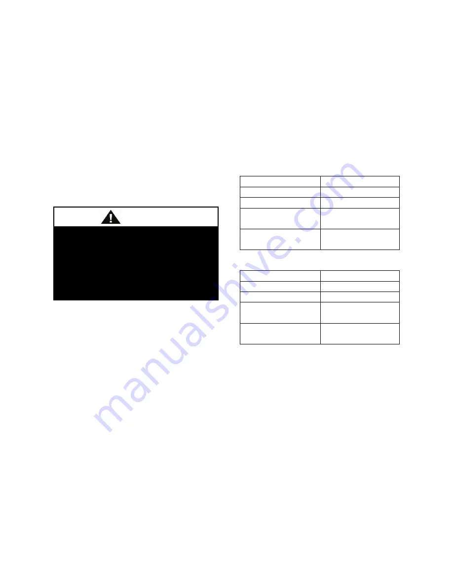
Table 33 - Gas Piping Supports (Metric)
Pipe Size
Support Intervals
12.7 to 19.1
Every 1.8 m
19.1 to 25.4
Every 2.4 m
44.5 or Larger
(Horizontal)
Every 3 m
31.75 or Larger
(Vertical)
Every Floor
Table 34 - Gas Piping Supports (Imperial)
Pipe Size
Support Intervals
1/2” to 3/4”
Every 6 ft
3/4” to 1”
Every 8 ft
1-3/4” or Larger
(Horizontal)
Every 10 ft
1-1/4” or Larger
(Vertical)
Every Floor
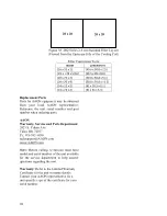
Additional Gas Piping Considerations
Local codes will usually require a field
provided and installed manual main shutoff
valve and union external to the unit. Main
shutoff valve shall be labeled. A drip leg shall
be installed near the unit connection to trap
sediment and condensate. Pipe joint
compounds used on all gas piping
connections shall be resistant to liquid
petroleum gases. If flexible gas piping to the
unit, or in the unit, must be replaced
connectors cannot be reused, only new
connectors may be used.
Heat exchanger comes equipped with a
condensate drain which shall be plumbed to
the appropriate drain according to the (United
Heater shall be disconnected from the
gas supply piping during pressure
testing of the supply piping system with
pressures in excess of 3.5 kpa (½ psi).
Gas valves can be damaged if
subjected to more than 3.5 kpa (½ psi).
CAUTION
Summary of Contents for RQ NextGen Series
Page 2: ......
Page 26: ...26 Figure 3 RQ Cabinet Standard and Power Exhaust Gasket Locations...
Page 40: ...40 Figure 23 Post Corner Hole Piping Figure 24 Post Back Hole Piping...
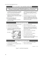
Page 88: ...88 Gas Heater Operating Instructions Figure 36 Gas Heater Instructions...
Page 95: ...95...
Page 96: ...96...
Page 105: ...105 Maintenance Log E Coated Coil...
Page 107: ...107...


