


81
9
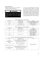
= Short or overload on the 0-10VDC
analog signal output
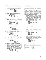
Operation
Controller receives 24VAC preheat enable
Controller evaluates if outside air
temperature “OAT” is below setpoint
‘OATset’
If OAT < ‘OATset’, controller will delay
heating startup by time setpoint
‘STARTDLY’, then stage up preheat to
maintain the setpoint ‘LATset’ to a
maximum number of stages set in setpoint
‘Stages’.
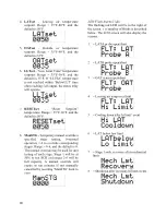
If a safety is reached with the controller’s
safety sensors then the electric preheat will be
de-energized for a period of 2 minutes.
Electric preheat will turn on stage one at
100% for 3 minutes to test if fault conditions
still exist after the cool down period. The
controller will repeat this and if 3 trips are
recorded in 60 minutes then the controller
will lockout and require manually cycling
power to reset.
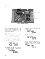
The modulating electric preheat option is
designed to temper the incoming outside air
to the unit based on an enable control signal
and the outside air conditions.
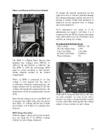
A 24VAC enable signal must be provided to
the [PHE] terminal to enable the operation of
the electric preheat. Once the preheat
controller is enabled it will monitor the
outside air temperature to determine if any
capacity of preheat is needed. If the outside
air temperature falls below the outside air
temperature setpoint the electric preheat will
be started up and maintain the leaving air
temperature setpoint with both SCR
controlled and staged electric preheat. Both
setpoints are set with push button LCD
interface on the preheat controller. Outside
air temperature sensors and preheat discharge
supply air temperature sensors are factory
installed and wired to the preheat controller.
Electric preheat has maximum operating
outside air temperature of 15.6
°
C (60°F) and
a maximum preheat discharge air
temperature of 26.7
°
C (80°F).
[COM], [PHO] & [PHC] feedback terminals
are provided to communicate if the electric
preheat is in operation. PHO is a normally
open contact, PHC is a normally closed
contact, and COM is the common. These
terminals are not required to be connected.
[PHE] is the electric preheat operation
enable. [PH+] and [PH-] are the preheat set
point reset terminals.
Gas Heating
Verify the unit nameplate agrees with the
proper gas supply type and amount.
Gas piping shall be installed in accordance
with local codes, or in the absence of local
codes, installation shall conform to the
current (United States) National Fuel Gas
Code ANSI-Z223.1/NFPA 54 or the current
(Canada) National Fuel & Propane
Installation Code CSA B149.1 or B149.2.
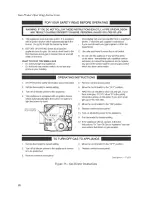
FOR YOUR SAFETY
Read the entire gas heating
installation section of this manual
before beginning installation of the
gas heating section.
If you do not follow these instructions
exactly, a fire or explosion may result
causing property damage, personal
injury, or loss of life.
WARNING
Summary of Contents for RQ NextGen Series
Page 2: ......
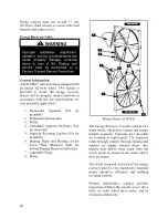
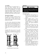
Page 26: ...26 Figure 3 RQ Cabinet Standard and Power Exhaust Gasket Locations...
Page 40: ...40 Figure 23 Post Corner Hole Piping Figure 24 Post Back Hole Piping...
Page 88: ...88 Gas Heater Operating Instructions Figure 36 Gas Heater Instructions...
Page 95: ...95...
Page 96: ...96...
Page 105: ...105 Maintenance Log E Coated Coil...
Page 107: ...107...


