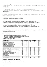
11
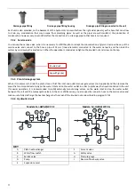
Each
unit
is
also
provided,
on
the
basement
of
the
hydronic
kit
(accessible
from
the
right
sides
panels),
with
a
hole
that
can
allow
to
drain
any
condensation
that
may
escape
from
plumbing
pipes.
As
well
as
the
pipes
are
well
‐
insulated,
the
production
of
condensate
is
however
very
low
and
therefore
the
connection
of
a
drainage
pipe
to
that
hole
is
not
required.
7.4.2
Service
valve
You
can
use
the
service
valve,
when
it
is
necessary
to
refill
the
plant
or
adapt
the
concentration
of
glycol.
Unscrew
the
cap
of
the
service
valve
and
connect
to
the
hose
a
pipe
of
14
mm
(inner
diameter)
connected
to
the
water
network,
and
then
load
the
system
by
unscrewing
the
knurled
nut.
When
the
operation
is
concluded,
retighten
the
knurled
nut
and
screw
on
the
cap.
7.4.3
Plant
drainage
system
When
it
is
necessary
to
drain
the
plant,
close
at
first
the
inlet
and
outlet
manual
gate
valves
(not
supplied)
and
then
remove
the
pipes
that
are
disposed
externally
on
the
water
inlet
and
on
the
water
outlet
in
order
to
spill
away
the
liquid
contained
in
the
unit
(for
easier
operation,
it
is
recommended
to
install
externally
two
draining
valves,
on
the
water
inlet
and
on
the
water
outlet,
between
the
unit
and
the
manual
gate
valves).
In
the
case
of
V2+
series,
you
also
need
to
connect
a
hose
to
the
service
valve
and
make
sure
to
fully
discharge
the
heat
exchanger
by
the
mean
of
the
knurled
nut
as
described
in
paragraph
7.4.2.
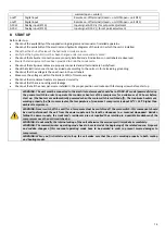
7.4.4
Hydraulic
circuit
Models:
N
‐
i
‐
HWAK/WP
V2
Models:
N
‐
i
‐
HWAK/WP
V2+
A
B
H
F
G
E
D
C
A
B
H
F
G
E
D
I
C
KEY
A
Plate
heat
exchanger
F
Air
vent
valve
B
Water
flow
switch
G
Safety
valve
C
Service
valve
H
Pressure
gauge
D
Pump
I
Reverse
‐
flow
4
‐
way
valve
E
Expansion
vessel
Drainage
pipe
fitting
Drainage
pipe
fitting
housing
Drainage
pipe
fitting
connected
to
the
unit
Cap
with
gasket
Knurled
nut
Summary of Contents for HPE Series
Page 21: ......
Page 29: ...28 ...
Page 31: ...30 16 WATER PUMP CURVES 16 1 MODELS HPE 06 09 16 2 MODELS HPE 12 15 ...
Page 34: ...33 19 3 HPE 12 15 IN OUT 1 M ...
Page 35: ...34 20 WIRING DIAGRAMS 20 1 MODELS HPE 06 09 ...
Page 36: ...35 20 2 MODEL HPE 12 ...
Page 37: ...36 20 3 MODEL HPE 15 ...
Page 43: ...NOTE ...
Page 44: ...NOTE ...
Page 45: ...NOTE ...
Page 46: ...NOTE ...
Page 47: ......


