14
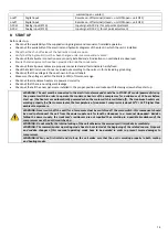
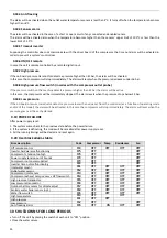
summer/open
=
winter)
onoff
Digital
input
Remote
on
‐
off
terminal
(closed
=
unit
ON/open
=
unit
OFF)
onoff
Digital
input
Remote
on
‐
off
terminal
(closed
=
unit
ON/open
=
unit
OFF)
0
‐
10V+
Analog
input
(ST10)
Input
signal
0
‐
10V
(+)
for
set
point
adjustment
0
‐
10V
‐
Analog
input
(ST10)
Input
signal
0
‐
10V
(
‐
)
for
set
point
adjustment
8
START
UP
Before
start
‐
up:
•
Check
out
the
availability
of
the
supplied
wiring
diagrams
and
manuals
of
installed
apparatus.
•
Check
out
the
availability
of
the
electrical
and
hydraulic
diagrams
of
the
plant
in
which
the
unit
is
installed.
•
Check
that
the
shut
‐
off
valves
of
the
hydraulic
circuits
are
open.
•
Verify
that
the
hydraulic
circuit
has
been
charged
under
pressure
and
air
vented.
•
Check
out
that
all
water
connections
are
properly
installed
and
all
indications
on
unit
labels
are
observed.
•
Ensure
that
arrangements
have
been
provided
to
drain
the
condensate.
•
Check
out
that
all
power
cables
are
properly
connected
and
all
terminals
are
hardly
fixed.
•
Check
that
electrical
connections
are
carried
out
according
to
the
norms
in
force
including
grounding.
•
Check
out
that
the
voltage
is
the
one
shown
in
the
unit
labels.
•
Make
sure
the
voltage
is
within
the
limits
(±
10%)
of
tolerance
range.
•
Check
out
that
crankcase
heaters
are
powered
correctly.
•
Check
out
that
there
is
no
refrigerant
leakage.
•
Check
out
that
all
the
cover
panels
are
installed
in
the
proper
position
and
locked
with
fastening
screws
before
start
up.
WARNING:
The
unit
must
be
connected
to
the
electrical
network
and
should
be
in
STAND
‐
BY
mode
(powered)
closing
the
general
switch
in
order
to
operate
the
crankcase
heaters
of
the
compressor
for
a
minimum
of
12
hours
before
start
up.
(the
heaters
are
automatically
powered
when
the
main
switch
is
switched
off).
The
crankcase
heaters
are
working
properly
if,
after
some
minutes,
the
temperature
of
crankcase’s
compressor
is
about
10°C
÷
15°C
higher
than
ambient
temperature.
WARNING:
Never
switch
off
the
unit
(for
a
temporary
stop)
by
switching
off
the
main
switch:
this
component
should
be
used
to
disconnect
the
unit
from
the
power
supply
only
for
lengthy
stoppages
(e.g.
seasonal
stoppages).
Besides,
failing
the
power
supply,
the
crankcase’s
resistances
are
not
supplied
thus
resulting
in
a
possible
breakdown
of
the
compressors
once
the
unit
is
switched
on.
WARNING:
Do
not
modify
the
internal
wiring
of
the
unit
otherwise
the
warranty
will
terminate
immediately.
WARNING:
The
summer/winter
operating
mode
have
to
be
selected
at
the
beginning
of
the
related
season.
Frequent
and
sudden
changes
of
this
seasonal
operating
mode
have
to
be
avoided
in
order
to
prevent
severe
damages
to
compressors.
WARNING:
When
you
first
install
and
start
‐
up
the
unit
make
sure
that
the
unit is
working
properly
in
both
cooling
and
heating
modes.
Summary of Contents for HPE Series
Page 21: ......
Page 29: ...28 ...
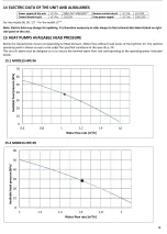
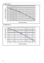
Page 31: ...30 16 WATER PUMP CURVES 16 1 MODELS HPE 06 09 16 2 MODELS HPE 12 15 ...
Page 34: ...33 19 3 HPE 12 15 IN OUT 1 M ...
Page 35: ...34 20 WIRING DIAGRAMS 20 1 MODELS HPE 06 09 ...
Page 36: ...35 20 2 MODEL HPE 12 ...
Page 37: ...36 20 3 MODEL HPE 15 ...
Page 43: ...NOTE ...
Page 44: ...NOTE ...
Page 45: ...NOTE ...
Page 46: ...NOTE ...
Page 47: ......


