17
‐
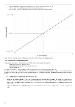
if
this
input
is
at
0
volts
you
will
have
the
actual
set
point:
set
point
(Coo/Hea)
‐
b15/2
‐
if
the
input
is
at
5
volts
the
set
point
will
be
the
set
one
(Coo/Hea)
‐
if
the
input
is
10
volts
you
will
have
the
actual
set
point:
set
point
(Coo/Hea)
+
b15/2
The
0
‐
10V
signal
must
be
applied
to
the
terminals
0
‐
10V
+
and
0
‐
10V
‐
(see
the
wiring
diagrams).
9.6
HYDRAULIC
PUMP
OPERATION
The
hydraulic
pump
can
be
set
according
to
one
of
the
three
following
types
of
operation:
‐
Operation
by
thermoregulator
(default)
‐
Operation
by
thermoregulator
with
periodic
activation
‐
Continuous
operation
The
pump
is
switched
off
immediately
with
the
alarm
activation
of
the
flow
switch
with
manual
reset.
The
pump
is
always
turned
on
if
the
antifreeze
resistances
are
running
or
when
the
hydraulic
pump
operates
in
antifreeze
mode
(is
enabled
if
the
water
regulation
temperature
decreases
below
8°C,
is
disabled
if
the
water
regulation
temperature
increases
above
10°C).
9.6.1
OPERATION
BY
THERMOREGULATOR
(Default)
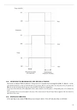
During
this
operating
mode
(
P03
=
1
,
default),
the
thermoregulator
actuates
the
pump;
after
a
time
delay
of
20
seconds
from
actuation
of
the
pump,
the
compressor
also
will
be
activated.
However,
in
power
off
case,
the
pump
turns
off
with
a
delay
time
of
120
seconds
after
the
thermoregulator
is
in
off
state
(the
off
mode
corresponds
to
the
turning
off
state
of
the
compressor).
In
the
case
of
the
activation
of
the
flowswitch
alarms
with
automatic
reset
the
pump
is
still
operating
even
if
the
compressor
is
off.
Summary of Contents for HPE Series
Page 21: ......
Page 29: ...28 ...
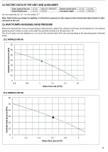
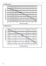
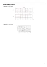
Page 31: ...30 16 WATER PUMP CURVES 16 1 MODELS HPE 06 09 16 2 MODELS HPE 12 15 ...
Page 34: ...33 19 3 HPE 12 15 IN OUT 1 M ...
Page 35: ...34 20 WIRING DIAGRAMS 20 1 MODELS HPE 06 09 ...
Page 36: ...35 20 2 MODEL HPE 12 ...
Page 37: ...36 20 3 MODEL HPE 15 ...
Page 43: ...NOTE ...
Page 44: ...NOTE ...
Page 45: ...NOTE ...
Page 46: ...NOTE ...
Page 47: ......


