16
9.4
DYNAMIC
SET
‐
POINT
ADJUSTING
The
controller
can
change
the
set
‐
point
by
adding
a
value
depending
on
the
outdoor
air
temperature
sensor.
In
this
case,
you
need
to
change
the
values
of
the
parameters
from
b08
to
b14
following
the
indications
below
(settings
to
be
done
by
the
installer):
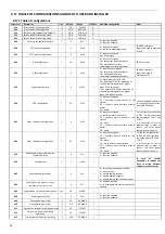
Prameters
of
the
controller
PAr
‐
>rE
‐
>
•
b08
=
dynamic
set
‐
point,
enabled
= 1
/
unabled
=
0
(must
be
disabled
in
the
case
of
the
use
of
climatic
compensation
from
the
optional
remote
keyboard
CRH).
• b09
=
offset
max
in
cooling
mode
operation.
• b10
=
offset
max
in
heating
mode
operation.
• b11
=
Outdoor
temperature
setting
in
cooling
mode.
• b12
=
Outdoor
temperature
setting
in
heating
mode.
• b13
=
Temperature
difference
in
cooling
mode
operation.
• b14
=
Temperature
difference
in
heating
mode
operation.
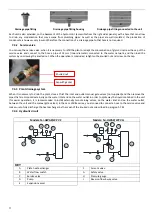
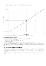
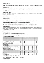
Curve
of
the
set
‐
point
variation
as
a
function
of
the
outside
temperature:
9.5
0
‐
10V
ANALOG
INPUT
FOR
SET
‐
POINT
REGULATION
Another
type
of
setting
that
allows
to
change
the
set
‐
point
by
adding
(or
subtracting)
a
value
in
function
of
the
0
‐
10V
analog
input
(if
enabled).
To
enable
the
function,
you
must
set
H21
=
40
,
and
change
the
values
of
the
parameter
b15
(range
0
‐
10),
taking
into
account
that:
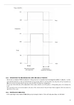
Temperature
Summary of Contents for HPE Series
Page 21: ......
Page 29: ...28 ...
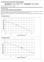
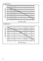
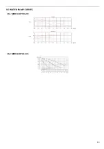
Page 31: ...30 16 WATER PUMP CURVES 16 1 MODELS HPE 06 09 16 2 MODELS HPE 12 15 ...
Page 34: ...33 19 3 HPE 12 15 IN OUT 1 M ...
Page 35: ...34 20 WIRING DIAGRAMS 20 1 MODELS HPE 06 09 ...
Page 36: ...35 20 2 MODEL HPE 12 ...
Page 37: ...36 20 3 MODEL HPE 15 ...
Page 43: ...NOTE ...
Page 44: ...NOTE ...
Page 45: ...NOTE ...
Page 46: ...NOTE ...
Page 47: ......


