background image

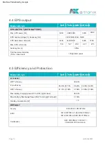
Model  AX,  1ph

battery

PV

Model  AX,  1ph

Max.  DC  voltage  [V]

20/20

Operating  temperature  [°C]

360

Max.  input  current  (input  A /  input  B)  [A]

80-550

Battery  voltage  range  [V]

Yes

Max.  regenerative  current  of  the  inverter

2

Battery  type

Max.  charging  current  [A]

-20  ~  +50

MPPT  voltage  range  [V]

Optional

LFP

CAN/RS485

Max.  recommended  DC  power  [W]

16/16

Strings  per  MPP  tracker

300Vdc

Reverse  polarity  protection

Nominal  DC  operating  voltage  [V]

0

600

40

Storage  temperature  [°C]

Max.  short-circuit  current  (input  A /  input  B)  [A]

100

Recommended  battery  voltage  [V]

-10  ~  +50

to  array  [mA]

1

Max.  discharge  current  [A]

Switch-on  voltage  [V]

Number  of  MPP  trackers

80-480

Communication  interfaces

DC  switch

40

Operating  instructions  

a-TroniX  inverter  AX  series,  1ph

3kW  3.7kW  4.6kW  5kW  6kW

3kW  3.7kW  4.6kW  5kW  6kW

4.  Technical  data

4.1  PV  input  (only  for  hybrid)

4.2  Battery

A:2250

B:2250

7500

5500

A:3750

A:2750

B:3750

B:2750

9000

6900

A:4500

A:3450

B:4500

B:3450

4500

page  12

atx009de0823

Machine Translated by Google

Summary of Contents for AX Series

Page 1: ...INVERTER atx009de en0823 Installation and operating instructions AX series 1ph Machine Translated by Google...

Page 2: ...an be read without Connection path 23 D 25469 Halstenbek GERMANY may be changed with prior notice but there is no obligation to continually update it Design and equipment changes that improve the prod...

Page 3: ...ation 7 1 Control panel 5 3 Assembly 7 2 Function tree 6 Electrical connection 8 Maintenance 8 1 Overview of error codes 6 1 PV connection only for hybrid 8 2 Troubleshooting and routine maintenance 9...

Page 4: ...eep these instructions so that they are accessible at all times The inverter complies with the requirements of the applicable CE guidelines DANGER This symbol indicates texts hints or tips 1 1 Scope 1...

Page 5: ...ngs in this installation manual Installation and operation may result in serious safety hazards electric shock hazards or equipment damage Danger of electric shock All work including transport install...

Page 6: ...ce if the safety devices are not working or an authorized AKKU SYS service representative Capacitive leakage current The leakage current is mainly caused by the parasitic Residual current In the event...

Page 7: ...ter DC High quality RCD circuit breakers usually trip at a value that regulations are required The installation of an RCD circuit breaker must is closer to its nominal value Protects against electric...

Page 8: ...erter and the PV generator when the voltage protection level VP of the surge arresters is greater than 1100V an additional SPD type 3 is required for overvoltage protection for electrical devices The...

Page 9: ...depends on the PV energy and user s preferences Advanced anti islanding solutions Max efficiency up to 97 8 EU efficiency up to 97 0 THD 3 Touch buttons Power factor control User friendly HMI PC remo...

Page 10: ...uired in EPS mode Priority Load Grid Battery In the case of the external generator the electricity generated is first used to supply local consumers and then fed into the public grid The battery is ch...

Page 11: ...nly for Hybrid H I Article PV2 Only for Hybrid Waterproof lock valve J Battery connections DRM Measuring device CT RS485 Grounding screw L M PARALLEL 1 N PARALLEL 2 D A NOTICE Only authorized personne...

Page 12: ...Nominal DC operating voltage V 0 600 40 Storage temperature C Max short circuit current input A input B A 100 Recommended battery voltage V 10 50 to array mA 1 Max discharge current A Switch on volta...

Page 13: ...rrent A 0 8 leading to 0 8 lagging 10000 Max AC apparent power VA 6000 50 60 5 13 6 35 Max AC current A 12000 3300 Nominal mains voltage AC voltage range V 23 0 16 7 57 4 27 3 4048 AC rated current A...

Page 14: ...efficiency 97 04 EN 62109 1 EN 62109 2 6000 Max EPS current A Total harmonic distortion 97 00 IEC EN 61000 6 3 IEC EN 61000 6 4 16 7 2 rated power 95 26 95 70 Max battery charging power PV to BAT ful...

Page 15: ...t LCD app website 2000 Inverter topology IP65 for outdoor use WLAN LAN 4G GPRS optional I 35 Dimensions W x H x D mm DRM USB CT III AC II DC Net weight kg communication Humidity LCD display 434 418 18...

Page 16: ...negative Measuring device optional CT extension plug Installation Guide 5 Installation Expansion tubes expansion screws Quick installation guide Object quantity description CT with 10m cable Ground c...

Page 17: ...m above sea level Not in direct sunlight The slope of the wall should be within 5 A Solid brick concrete or equivalent mounting surface Not in an environment with precipitation or high humidity 95 Not...

Page 18: ...t tilt the energy storage unit forward horizontally upside down backwards or sideways Installation space requirements When installing the energy storage device ensure that there are no other devices f...

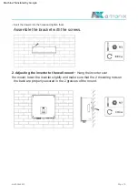
Page 19: ...2 Adjusting the inverter to the wall mount Hang the inverter over the mount lower the inverter slightly and make sure that the 2 mounting rods on the back are properly secured in the 2 grooves of the...

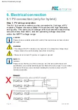
Page 20: ...DC switch The voltage of the PV modules is very high and is in a dangerous voltage range Please observe the electrical safety rules when connecting Please do not connect PV positive or negative to gro...

Page 21: ...elect 12 AWG wire for connecting the PV module Pass the pin contact through the cable nut and mount it on the back of the plug or socket If you feel or hear a click the pin contact assembly is properl...

Page 22: ...nductor strands are captured in the pin contact Back of the plug or socket If you feel or hear a click the pin contact assembly is properly seated Turn off the DC switch Choose 8 AWG wire for connecti...

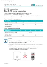
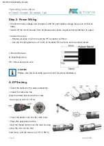
Page 23: ...t use the EPS function the core area may change The AX1ph series inverters are designed for single phase networks be installed between the inverter and the grid and the current of the 3 A micro switch...

Page 24: ...age range see technical data Please note the local cable type and color for actual installation screw the lock nut into that Switch off the circuit breaker from all phases and secure it against being...

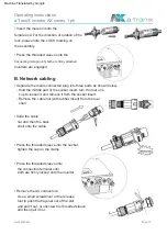
Page 25: ...loosen it and remove it from the socket insert Connecting terminal until both are firmly attached Press the threaded sleeve onto the connection terminal until both are firmly locked onto the inverter...

Page 26: ...e can be purchased from your local supplier Bottom of the inverter Connection steps 3 For WiFi device Connect the WiFi device to the local router and 1 For LAN device Complete the cabling between the...

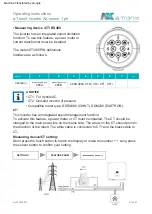
Page 27: ...of the mesh The white cable is connected to CT and the black cable to CT Measuring device CT setting The meter CT 485 PIN definitions This inverter has an integrated export management function CT1 Fo...

Page 28: ...n To use this function a power meter or current transformer must be installed Please install the device on the network site Serial RS485 A NOTICE USB port For accurate reading and control of power a m...

Page 29: ...a TroniX inverter AX series 1ph Page 29 atx009de0823 Counter Type DDSU666 CHINT Setting the export limit A NOTICE The ammeter is connected as follows PARM EXPORT CONTROL SETTINGS ON NET xxxxxW Machin...

Page 30: ...1 Insert the cable connector into the BMS port on the bottom of the inverter and screw it tight Step 2 Crimp the cable with an Rj45 connector located inside the cable connector Step 3 The communicati...

Page 31: ...ions imposed by other active DRMs Operating instructions a TroniX inverter AX series 1ph 7 3 8th 4 5 1 function 6 2 The DRM supports multiple demand response modes by issuing control signals as descri...

Page 32: ...ble connector and run the network cable Step 1 Unscrew this plate from the inverter ESTOP Close the inverter Step 3 Insert the cable connector into the DRM COM port on the bottom of the inverter and s...

Page 33: ...ration ensure that the power of the EPS loads is lower EPS mode can be achieved by two different types of wiring On the one hand the internal bypass can be used to connect the home emergency call load...

Page 34: ...that the instantaneous power of the load at startup is less than the maximum power of EPS mode In the following table you will find some conventional and sensible loads for reference Please refer to...

Page 35: ...ains is switched off For countries such as China Germany Czech Republic Italy etc please follow local wiring regulations The neutral conductor of the alternative power supply must be isolated or switc...

Page 36: ...tery breaker Internal Please note the following steps for commissioning the inverter circuit breaker and the battery circuit breaker The EPS function is turned off by default when opened 1 Make sure t...

Page 37: ...7 1 Control panel Move cursor up or increase value The inverter is in fault mode Move cursor down or decrease value OK button Confirm the selection The inverter is normally connected to the battery D...

Page 38: ...atx009de0823 Page 38 Operating instructions a TroniX inverter AX series 1ph 7 2 Function tree Machine Translated by Google...

Page 39: ...r Mains frequency out of range DC component in the output current is outside the limit Check whether the battery input voltage is within the normal range Grid loss error Mistake Iso Or seek help from...

Page 40: ...Temp Battery power is low Wait until the battery is recharged Or seek help from us Mistake The connection has failed Check the voltage of the neutral conductor and PE Check AC wiring Disconnect the P...

Page 41: ...help from us if you cannot return to normal Bat relay open Disconnect the PV grid and battery and then reconnect them Disconnect the PV grid and battery and then reconnect them Bat Buck Disconnect the...

Page 42: ...you cannot return to normal Check whether the communication cable between the meter and the inverter Disconnect the PV grid and battery and then reconnect them Or seek help from us if you cannot retur...

Page 43: ...liers to match BMS Int The slave software and hardware do not match BMS temp high Battery hardware under protection Please contact battery suppliers BMS TempSen error to match The software between mas...

Page 44: ...or code on the inverter information panel If a message appears write it down before taking any further action 6 Are the display panel and communication cable connected correctly and undamaged b Try th...

Page 45: ...il the inverter is completely de energized Store the inverters in a dry place where the ambient temperature is always between 40 C and 70 C Please ensure that the inverters are kept no more than 4 box...

Page 46: ...umulator and Battery Technology Nord GmbH Connection path 23 25469 Halstenbek GERMANY Phone 49 4101 37676 0 info akkusys de www akkusys de akkusys shop www a tronix de www a tronix de Machine Translat...

Page 47: ...INVERTERS atx009en0823 Page 47 User Manual AX series 1ph Machine Translated by Google...

Page 48: ...ormity and warranty conditions can be found on All rights reserved The publication and copyright of this documentation remain with the company AKKU SYS Accumulator and Battery Technology Nord GmbH www...

Page 49: ...2 91 6 5 Electrical Connection 60 68 83 4 1 PV Input For 3ph Only 6 7 System Connection Diagrams 6 8 Inverter Start Up 6 9 Inverter Switch Off 61 72 85 5 Installation 7 1 Control Panel 4 Technical dat...

Page 50: ...r of high voltages GRADE The Symbol indicates a hazardous situation which if not avoided will result in death or serious injury Danger to life due to high voltages in the inverter Please keep this man...

Page 51: ...tion must be made only by qualified technical personnel Do not install the equipment in adverse environmental conditions such as in close proximity to flammable or explosive substances in a corrosive...

Page 52: ...he manufacturer about non standard installation conditions PV System Residual Current Factors In every PV installation several elements contribute to the current leakage to protective earth PE these e...

Page 53: ...he use of a type A RCD Unless a lower value is required by the specific local electrical codes Suggests an RCD value between 100mA and 300mA 1 Selecting the appropriate RCD is important for correct op...

Page 54: ...PD test impulse D1 for signal line according to EN 61632 1 All DC cables should be installed to provide as short a run as possible and positive and negative cables of the string or main DC supply shou...

Page 55: ...to AC energy and store energy into battery The inverter can be used to optimize self consumption store in the battery for future use or feed in to public grid Utilizes the latest high efficiency powe...

Page 56: ...de When no PV supplied battery will discharge for local loads firstly and grid will supply power when the battery capacity is not enough Feed in priority Priority load grid battery Force time use Prio...

Page 57: ...For Hybrid Only Waterproof lock valve L DRM PV1 For Hybrid Only M Grounding screw PV2 For Hybrid Only N Battery connector PARALLEL 1 G Meter CT RS485 PARALLEL 2 C D WiFi 4G USB E A BMS F GRADE K b On...

Page 58: ...tection Operating temperature C B 4500 A 2250 600 MPPT voltage range V 2 No of MPP trackers Battery type CAN RS485 7500 B 3450 Max short circuit current input A input B A B 2250 5500 80 550 Max charge...

Page 59: ...7 Total harmonic distortion 9200 10000 4600 Max AC current A 16 7 13 6 130A 10us 0 8 leading to 0 8 lagging 57 4 7680 Rated grid frequency Hz 4048 23 0 3300 Max apparent AC power VA 220 230 240 180 to...

Page 60: ...battery discharge efficiency Total harmonic distortion IEC EN 61000 6 3 IEC EN 61000 6 4 EN 62109 1 EN 62109 2 20ms 5000 Euro efficiency 97 01 97 08 97 04 Max battery charge efficiency PV to BAT full...

Page 61: ...Non Isolated LCD app website 0 100 non condensing Inverter topology IP65 2000 WiFi LAN 4G GPRS optional Class I Dimension W H D mm DRM USB CT Operating temperature range C 35 Weight kg Communication...

Page 62: ...xtension connector Battery pin contacts 1 positive 1 negative 2 positive 2 negative Meters Optional Battery connectors PV pin contacts for hybrid only 5 1 Check for Physical Damage 5 2 Packing List Co...

Page 63: ...C Not in direct sunlight The slope of the wall should be within 5 Not in areas where highly flammable materials are stored The wall hanging the inverter should meet conditions below 1 Solid brick con...

Page 64: ...ll bit set 8mm Crimping pliers Stripping pliers Screwdriver Place the bracket on the wall and mark the position of the 5 holes from bracket Install the bracket with the expansion screws Drill holes wi...

Page 65: ...ith wall bracket Hang the inverter over the bracket slightly lower the inverter and make sure the 2 grooves on the back are fixed with the 2 mounting bars from bracket properly Fixing inverter with th...

Page 66: ...e cable and reduce DC loss we recommend installing the inverter as close to the PV modules as possible GRADE Please choose a suitable external DC switch if the inverter does not have a built in DC swi...

Page 67: ...e into back of the male or female plug When you feel or hear a click the pin contact assembly is seated correctly Crimp pin contact by using a crimping plier Choose 12 AWG wire to connect the PV modul...

Page 68: ...and ensure all conductor strands are captured in the pin contact When separating the DC connector push the tool down from the top Unlock the DC connector Separate the DC connector battery as below Use...

Page 69: ...meters of table 1 device is referred to the table above any load SHOULD NOT be 2 If you use the EPS function the wiring conduct core section can refer to AX1ph series inverters are designed for single...

Page 70: ...cuit breaker from all the phases and secure against Please refer to local cable type and color for actual installation reconnection Trim the wires Run the cable into the sleeve assembly Trim all the w...

Page 71: ...ark on the assembly Press the bayonet out of the slot with a small screwdriver or the unlock tool and pull it out or unscrew the threaded sleeve then pull it out Slide the cable groove Push the thread...

Page 72: ...device into WiFi LAN 4G port at the bottom of the Screw the ground screw with screwdriver as shown below the monitoring user manual for more details The inverter has an interface for WiFi LAN 4G devi...

Page 73: ...ust be installed The CT should be clamped on the main live line of the grid side The arrow on the CT should be pointing towards the grid The white cable connects to CT and the black cable connects to...

Page 74: ...ices The inverter has integrated export limitation functionality RS485 Meters optional USB serial port For a precise reading and control of power a meter can be used instead of a CT If the CT is fitte...

Page 75: ...Export limitation setting Meter type DDSU666 CHINT The electricity meter is connected as follows GRADE SETTINGS xxxxxW ON GRID PARM EXPORT CONTROL Page 75 atx009en0823 Machine Translated by Google...

Page 76: ...Prepare a standard network cable and cable connector then insert the network cable through the cable connector Step 2 Crimp the cable with a Rj45 plug which is inside of the cable connector Connection...

Page 77: ...are under development DRM6 Do not generate at more than 50 of rated power DRM PIN definition Do not generate at more than 75 of rated power and sink reactive power if capable DRM is provided to suppo...

Page 78: ...r device Step2 Generator Connect the generator and start up it Prepare a standard network cable and cable connector then insert the network cable Connection steps CAN External debug through the cable...

Page 79: ...bypass power GRADE 1 Under On grid mode please ensure that the EPS loads power is lower 3 We suggest not connect the inductive loads on EPS port EPS mode can be achieved by two different types of wiri...

Page 80: ...lower GRADE 1 EPS Box Optional Used for On Grid and EPS switching of inverters improve maximum EPS loads capacity maximum bypass current is 60A than the inverter s maximum output power Under EPS mode...

Page 81: ...e follow local writing regulations Neutral line of alternative supply must be isolated or switched Neutral line of alternative supply must be disconnected after the grid is off For countries such as A...

Page 82: ...witch for hybrid only AC breaker 2 Make sure all the DC wirings and AC wirings are completed correct EPS breaker and battery breaker 3 Make sure the meter is connected well Set the time on the inverte...

Page 83: ...connected to the battery Down button Confirm the selection Red OK button A G return Return the previous operation b Blue button H Green Move cursor to upside or increase value C Move cursor to downsid...

Page 84: ...Page 84 atx009en0823 7 2 Function Tree Machine Translated by Google...

Page 85: ...tem will reconnect if the utility is back to normal Disconnect PV grid and battery then reconnect Check if the battery input voltage is within the normal range Grid Freq SW Bus Vol The grid voltage is...

Page 86: ...al current is high Please check if the insulation of electrical wires is damaged Wait for a while to check if back to normal Or seek for help from us Fault Fault Fault PV voltage out of range Please c...

Page 87: ...sconnect PV grid and battery then reconnect Disconnect PV grid and battery then reconnect Res Cur HW Or seek help from us The eps relay failed Battery current high detected by hardware The master samp...

Page 88: ...interrupted Dci Cons The grid relay S1 keep close Fault Fault Or seek help from us if not go back to normal state Or seek help from us if not go back to normal state GridV Cons RDSP Smpl Or seek help...

Page 89: ...plier and well connected BMS Int Fault Unmatch The slave software and hardware do not match Check if the communication cable between BMS and inverter is correct NoAck BMS Volt High Battery over voltag...

Page 90: ...further assistance Please be prepared to describe details of your system installation and provide the model and serial number of the unit c If your inverter information panel is not displaying a fault...

Page 91: ...ons Please be sure to deliver any inverter that needs to be disposed from sites that are appropriate for the disposal in accordance with local regulations Check if the input and output wires are damag...

Page 92: ...a tronix de atx009de en0823 V1 0 AKKU SYS Accumulator and Battery Technology Nord GmbH Connection path 23 25469 Halstenbek GERMANY Telephone 49 4101 37676 0 info akkusys de www akkusys de akkusys sho...

Reviews: