background image

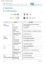
2.  Important  Safety  Instructions

operation  manual

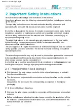
2.1  Transportation  and  Storage

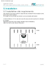
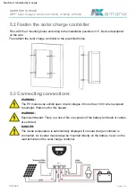
2.2  Installation  Notes

02/2022   

page  7

The  operating  instructions  must  be  read  and  understood  by  all  persons  and  

specialists  who  work  with  this  device  and  all  points  must  be  observed.

Any  further  use  or  use  that  goes  beyond  this  is  considered  to  be  improper  and  can  
lead  to  personal  injury,  damage  to  property  and/or  damage  to  the  device.

Always  store  the  device  and  the  corresponding  accessories  in  the  original  
packaging.

Do  not  try  to  disassemble  the  device.  It  contains  no  user-serviceable  parts.  During  
installation,  operation  or  maintenance  carried  out  by  qualified  personnel,  observe  

the  local  safety  instructions  and  the  relevant  laws.  Otherwise  personal  injury  or  

equipment  damage  may  occur.

The  safety  instructions  in  this  manual  serve  as  a  supplement  to  the  local  safety  
instructions.  Our  company  assumes  no  liability  for  damage  caused  by  non-

observance  of  the  safety  instructions.

Only  use  the  solar  charge  controller  in  connection  with  the  intended  photovoltaic  

systems.

Be  sure  to  follow  all  warnings  and  instructions  in  this  manual.

Only  transport  the  solar  charge  controller  in  the  original  packaging  to  protect  it  
from  bumps  and  knocks.

This  also  applies  if  no  regular  maintenance  or  maintenance/repairs  were  not  carried  
out  by  qualified  specialist  personnel.  The  device  must  also  be  set  up  by  qualified  

specialist  personnel.

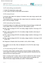
Before  installing  and  adjusting  the  solar  charge  controller,  be  sure  to  turn  off  the  
PV  modules.  Make  sure  the  circuit  breaker,  fuse,  or  disconnect  switches  on  the  
battery  terminals  are  turned  off.

Keep  them  safe  and  read  the  following  notes  carefully  before  installing  and  starting  
up  the  device.

The  device  must  be  protected  from  moisture  and  may  therefore  only  be  stored  in  
dry  rooms.

The  solar  charge  controller  may  only  be  used  in  photovoltaic  systems  that  correspond  
to  the  specifications  of  the  device  described  in  these  operating  instructions.  No  

other  energy  sources  may  be  connected  to  it.

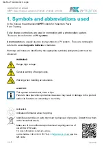
MPPT  Solar  Charge  Controllers  A100/20,  A100/40,  A150/60

Machine Translated by Google

Summary of Contents for A100/20

Page 1: ...rge controller 9887580 9887584 a TroniX MPPT Solar Charge Controller A100 20 a TroniX MPPT Solar Charge Controller A100 40 a TroniX MPPT Solar Charge Controller A150 60 item number 9887582 Model A100...

Page 2: ...weg 23 25469 Halstenbek Hamburg GERMANY Telephone 49 4101 3 76 76 0 Fax 49 4101 3 76 76 66 info akkusys de www akkusys de 02 2022 page 2 MPPT Solar Charge Controllers A100 20 A100 40 A150 60 The publi...

Page 3: ...ropriate information in these operating instructions Read carefully before use The solar charge controller is based on advanced MPPT technology specially developed for solar systems We assume no liabi...

Page 4: ...s A100 40 4 4 Installation positions A100 40 4 5 Dimensions A150 60 4 6 Installation positions A150 60 19 20 5 4 Connecting accessories 17 6 13 18 21 20 15 4 10 Bluetooth communication 16 Page 8 5 8 F...

Page 5: ...Solar Charge Controllers A100 20 A100 40 A150 60 27 32 25 6 11 Charging modes 23 26 6 3 LCD display 6 4 Error display 6 5 Parameter setting 6 6 Undervoltage protection 6 7 Reconnection voltage 6 8 Blu...

Page 6: ...this manual the abbreviation MPPT stands for Maximum Power Point Tracking A NOTICE Indicates information about recycling Warnings and notes are identified by the appropriate symbols pictograms and mu...

Page 7: ...safety instructions Only use the solar charge controller in connection with the intended photovoltaic systems Be sure to follow all warnings and instructions in this manual Only transport the solar c...

Page 8: ...fe is extended by a precise temperature sensor Batteries can produce flammable and possibly toxic gases oxyhydrogen Avoid creating any sparks near the battery The device has a double automatic protect...

Page 9: ...rent must be proportionately greater than the solar input current to balance the input and output power Monthly load data can be displayed as a summary in the form of graphics Always on dusk evening a...

Page 10: ...d the solar system The greater the difference between the battery voltage and the Vmp of the module the more energy is wasted In contrast to conventional PWM solar charge controllers pulse width modul...

Page 11: ...ed the PV charge current the solar charge controller will no longer be able to keep the battery at the float charge setpoint If the battery voltage remains below the quick recharge voltage the charge...

Page 12: ...ach full charge to avoid over voltage and or overheating of the battery Certain battery types benefit from periodic equalization charging WARNING By balancing the charge the battery voltage increases...

Page 13: ...ce description 4 1 Dimensions A100 20 operation manual Dimensions mm 02 2022 page 13 4 2 The installation position A100 20 MPPT Solar Charge Controllers A100 20 A100 40 A150 60 Machine Translated by G...

Page 14: ...4 3 Dimensions A100 40 4 4 Installation positions A100 40 operation manual 02 2022 page 14 Dimensions mm MPPT Solar Charge Controllers A100 20 A100 40 A150 60 Machine Translated by Google...

Page 15: ...4 5 Dimensions A150 60 4 6 Installation positions A150 60 operation manual page 15 02 2022 Dimensions mm MPPT Solar Charge Controllers A100 20 A100 40 A150 60 Machine Translated by Google...

Page 16: ...ble lengths must be ordered separately 6 RJ11 interface The sensor is connected via interface 5 2 plastic housings to protect internal components 3 LED LCD display to show settings and working status...

Page 17: ...LE technology A NOTICE 2 Realizes the solar charge controller wireless monitoring function There are two options For operation details refer to the Bluetooth app instructions The solar charge controll...

Page 18: ...around the device should be kept free for unhindered air circulation Attach it so that the cable holes are facing down Fix it upright on the wall Make sure that this is a non combustible wall material...

Page 19: ...h out for this hazard First drill the 4 mounting holes according to the installation positions in 5 Device description on the wall The inside temperature is automatically displayed if no solar charge...

Page 20: ...nominal voltage of 24 V DC the battery voltage should be in the range of 20 0 to 31 0 V DC To avoid tension in the cables wires first connect them to the load before connecting them to the solar charg...

Page 21: ...are in the immediate vicinity of the ATTENTION For systems with common negative poles such as mobile homes the use of a common negative pole solar charge controller is recommended device Keep a dista...

Page 22: ...V Module off undervoltage protection off overheat protection Flashing slowly 0 5 2 s Green on Short circuit or over current protection No communication Blink 0 5 0 5 s Flashing slowly 0 5 2 s The PV m...

Page 23: ...matically after 30 seconds PV Strom Simultaneously press the MENU and OK buttons for one second The LCD display stops scrolling Position pause display OK Set parameters Status Advertisement MENU Press...

Page 24: ...arge amp hours Status Temperature A NOTICE PV Module Symbol Battery type adjustable Load mode adjustable Total PV amp hours reconnection voltage LVR adjustable Last The PV ampere hours PV panel kit an...

Page 25: ...h the interface Battery status shows full error icon display battery frame flashes LCD display shows E4 order as follows Load off battery status shows empty error icon display battery frame flashes LC...

Page 26: ...LVD you must first increase the LVR value set the voltage protection of the solar charge controller The turn on voltage LVR should be at least 0 6 1 2 2 4V higher than the under voltage lockout LVD P...

Page 27: ...nfirm with OK to reset the set password via the mobile app When choosing a liquid gel or AGM battery the charging parameters boost equalize and float voltage can be set via mobile phone app RS485 or W...

Page 28: ...age Dusk to Sunrise The load output stays on from sunset to sunrise 12 24 V 10 32 V Standard 14 4 V The solar charge controllers of the a TroniX series are suitable for all types of lithium batteries...

Page 29: ...ht delay time 0 30 minutes default 0 30 minutes Dusk to Sunrise When the load is set to Dusk to Sunrise the day night threshold voltages and day night delay time can be set via RS485 or Bluetooth App...

Page 30: ...is switched on again Full protection against battery polarity reversal no damage to the solar charge controller Correct the connection to resume normal operation Battery low voltage Mistake Caused Ca...

Page 31: ...hort circuit occurs the load will short circuit while charging Description Damaged remote temperature sensor damaged the solar charge controller automatically adopts the internal temperature This prev...

Page 32: ...corrective action as soon as possible Make use of the certified and professional recycling service of our AKKU SYS team If necessary take corrective action Electric shock hazard Make sure all power i...

Page 33: ...n Twilight Night Manual before the boost or equalizer charging stage 14 14 8 28 29 6 25 C default 14 5 29 14 15 0 28 30 25 C default 14 8 29 6 Designation 4 17 per cell boost balance 3 33 per cell mai...

Page 34: ...uid AGM battery 13 14 5 26 29 39 43 5 52 58 25 C 0 83 99 9 Power connections mm Optional Own consumption mA 16 6AWG Standard 14 5 29 43 5 58 14 15 28 30 42 45 56 60 25 C Float Voltage V Maximum effici...

Page 35: ...0 64 0 Lithium Standard 29 4 Standard 8 16 24 32 loT 99 9 16 6AWG Lithium Standard 28 7 Permanent On Twilight Night Manual Ambient temperature C Bluetooth RS485 RJ25 6P2C interface IP32 low voltage P...

Page 36: ...talog Other manufacturers and product areas can be found in ours 02 2022 AKKU SYS Accumulator and Battery Technology North GmbH Verbindungsweg 23 25469 Halstenbek Hamburg GERMANY Telephone 49 4101 3 7...

Reviews: