background image

2

INTRODUCTION

HoloSea S7

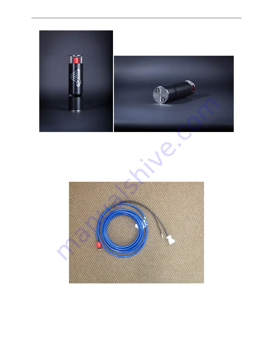
Figure 1: The preassembled HoloSea Microscope (vertical view in left panel and horizontal view in
right panel).

• Long (10m) cable with 13 pin connector to power laser, camera, and transmit data from the

camera to the host computer.

Figure 2: 10m Cable

• Power supply (12 VDC)

4

Summary of Contents for HoloSea S7

Page 1: ...HoloSea Microscope User Guide Model S7...

Page 2: ...er no tice in future editions Edition HoloSea Microscope User Guide Model S7 4Deep inwater imaging 6589 Chebucto Road Halifax Nova Scotia Canada B3L 1L9 Safety and Information Notices An Important sig...

Page 3: ...HoloSea Microscope iii...

Page 4: ...2 5 3 Sample Spacer 8 2 5 4 Crown 9 2 5 5 Purge Valves 9 3 Installation and Use 10 3 1 Connect the HoloSea cable 10 3 2 Screw on locking sleeve 11 3 3 Ethernet Connection 11 3 4 Testing and Deployment...

Page 5: ...ght panel and is attached to the microscope 11 11 Locking sleeve on both the cable left panel the microscope center panel and connected right panel 11 12 Use of female to female Ethernet connector In...

Page 6: ...e phase analysis many other applica tions 1 1 Purpose The HoloSea comes from a suite of instruments that all operate under proprietary digital inline holography technology platform developed by 4Deep...

Page 7: ...ng itself If properly assembled the light emitted from the laser should not pose any threat of long term damage to an exposed eye There are no user serviceable parts inside the light source If problem...

Page 8: ...s at the micron level foreign objects dust dirt fingerprints smudges perspiration saliva etc on the camera window and or the point source can greatly affect the quality of the captured holograms Take...

Page 9: ...sembled HoloSea Microscope vertical view in left panel and horizontal view in right panel Long 10m cable with 13 pin connector to power laser camera and transmit data from the camera to the host compu...

Page 10: ...CTION Figure 3 Power Supply 12 VDC Carrying case Figure 4 Carrying case with the microscope inside Please ensure all components listed above were shipped to you If not please contact a 4Deep represent...

Page 11: ...ection 3 1 Deployment rope cord to deploy the HoloSea Section 3 4 A female female Ethernet connector ex from a computer hardware store shown in Figure 12 Lint free wipes swabs ex Kim tech for use in c...

Page 12: ...l camera The camera s image sensor is protected by a sapphire glass window The sapphire window also has a copper ring around it to reduce the effect of biofouling on the instrument shown in Figure 6 T...

Page 13: ...s in inline holography Similar to the camera in Chamber 1 the point source is protected by a sapphire glass window see previous paragraph for care instructions 2 5 3 Sample Spacer The Sample Spacer pr...

Page 14: ...he bottom of the microscope The purge valves do not need to be used to ensure the microscope operates correctly If a 4Deep representative deems it necessary for the purge valves to be opened it will b...

Page 15: ...bout 1 10 of the female socket depth for a dry mating ie if the connector microscope is not being submerged for example when using the microscope in a laboratory environment Figure 9 Mating the underw...

Page 16: ...crew on locking sleeve Slide the locking sleeve over the cable connectors and screw it onto the bulkhead connector Figure 11 Locking sleeve on both the cable left panel the microscope center panel and...

Page 17: ...computer Connect the Ethernet end of the main cable to the Ethernet port on the computer Figure 13 Connecting to the computer Plug in the power adapter for the camera and plug in the laser power adap...

Page 18: ...e accurate imaging to be performed Figure 15 Deployment of the HoloSea from a wharf More complex deployment methods may also be necessary as researchers may wish to deploy the HoloSea in conjunction w...

Page 19: ...cables are properly attached and power is on Click Connect to Camera button to retry the connection Note it may take several seconds to connect to the camera For more help on connecting the camera see...

Page 20: ...ption for the HoloSea Settings Reconstruction Options Preset Figure 18 Select instrument preset dialog Go to Octopus User Guide for further details on capturing holograms Section 4 in the Octopus User...

Page 21: ...ra sensor Too many objects between the point source and the camera can reduce the amount of reference wave reaching the camera and will therefore result in poor reconstructions For moving objects keep...

Page 22: ...includes using an air duster to blow water away from crevices in the microscope 5 After EVERY deployment the sapphire windows need to be cleaned with window cleaner and lint free wipes Note that whil...

Page 23: ...urned out Send the microscope or point source back to the manufacturer for diagnosis Background light must be reduced to obtain optimal images Table 1 Common troubleshooting problems and solutions 6 A...

Page 24: ...and measuring particles in real time with the speed of up to 10 frames per second Octopus is a general purpose research grade software package that can reconstruct holograms acquired by the HoloSea ca...

Page 25: ...th 405 nm Power 5 Watts Power requirement 120 240 VAC Communication 13 pin SeaConn Ethernet connector Data transfer Gigabit Ethernet Computer operating system Windows 7 64 bit or later Hologram size 2...

Reviews: