


16
Step 2 - Install the Data Collector
Installation of Data Collector is intended to be performed by professional personnel.
The Data Collector must be installed in a cool dry location on site, and should be easily
accessible. Once the Data Collector is firmly fixed to a solid surface, you may make the
necessary cable connections as described and illustrated below.
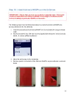
1.
Attach the antenna
to the antenna connector illustrated above. Use an
appropriate torque wrench set to 8 inch-pounds to ensure the connector is firmly
attached (but do not over tighten).
2.
Connect the Ethernet to a LAN
device
(router). For remote connectivity,
connect a standard CAT5 with RJ45 connector from the Ethernet port to router.
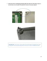
Make 2 loops of the Ethernet cable around ferrite core (Fair-Rite 0446167251
(1)
),
and secure the cable loops by clamping shut the ferrite core assembly.
3.
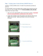
Connect DC Power (-48V) port to power source at the base of the tower
.
Once you have connected DC power to the Data Collector the
green power LED
next to the Antenna Connector will turn on. This indicates that the system has
power and the system software is loading.
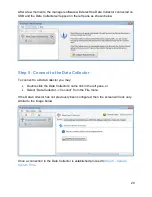
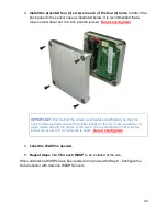
4.
Connect a USB cable from the PC to the Data Collector
using the device USB
port as shown above.
Attention:
The two USB Ports, 9-pin Serial Port, and Power Jack (5-12V) are only used
for system debug and configuration purposes. These ports are not to be connected to
any device during normal operation.
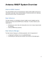
Summary of Contents for Antenna W.A.S.P.
Page 1: ...Antenna W A S P User s Guide...
Page 5: ...5 CE Mark Conformity...
Page 59: ...59 Technical Support Contacts...


