


1.
RS-485/422 Serial
(
COM1, COM2
)
2.
Ethernet port LED indicator
3.
Power LED indicator
4.
Serial receive data indicator
5.
Serial transmit data indicator
6.
Wall mounting installation
7.
10Base-T /100Base-TX Ethernet port
8.
DIP switch
9.
Power input 9~48VDC
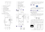
GW1102-2D (RS-232)-P(9~48VDC)
1.
RS-232 Serial
(
COM1, COM2
)
2.
Ethernet port LED indicator
3.
Power LED indicator
4.
Serial receive data indicator
5.
Serial transmit data indicator
6.
Wall mounting installation
7.
10Base-T /100Base-TX Ethernet port
8.
DIP switch
9.
Power input 9~48VDC
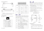
【
Appearance and dimension
】
Unit
(
mm
)
【
Power supply input
】
Front View Top View
GW1102 series provide DC power input, voltage input is the
two terminal form, plug type 2 core spacing of 5.08mm terminals,
wherein the power input range of 9 ~ 48VDC. (V+, V-)
【
DIP switch
】
Top panel provide 4 bit DIP switch to set function (ON is
effective), 1, 3, 4 is reserved, 2 is factory default, if you change
the DIP switch statue, please power off and power on.
【
Communication connector
】
The series products support 1 Ethernet ports and 2 serial ports
(RJ45 or 5 bit terminal interface).
10/100BaseT(X) Ethernet port
The pinout of RJ45 port display as below, connect by UTP or
STP. The connect distance is no more than 100m. 100Mbps is
used 120Ω of UTP 5; 10Mbps is used 120Ω of UTP 3, 4, 5.
RJ 45 port support automatic MDI/MDI-X operation. Can
connect the PC, Server, Converter and HUB .Pin 1,2,3,6
Corresponding connections in MDI. 1→3, 2→6, 3→1, 6→2 are
used as cross wiring in the MDI-X port of Converter and HUB.
10Base-T/100Base-TX are used in MDI/MDI-X, the define of Pin
in the table as below.
NO.
MDI signal MDI-X signal
1
TX+
RX+
2
TX-
RX-
3
RX+
TX+
6
RX-
TX-
4, 5, 7, 8
—
—
Note
:
“TX±”Transmit Data±
,
“RX±”Receive Data±
,
“—”Not Use.
1
8


