background image

EZPAN   EDGELIT PANEL  2X2              

INSTALLATION INSTRUCTIONS

Thank you for buying RAB lighting fixtures. Our goal is to design the best quality products to get the job done right. We’d like to hear your comments. 
Call the Marketing Department at 888-RAB-1000 or email: [email protected]

TM  

Access Plate

Conduit Knockouts

SAFETY INSTRUCTIONS

WARNING: Risk of fire or electric shock. Suitable for Damp locations. 
WARNING: Suitable for 9/16” or 15/16” Flat Tee Grid in both Insulated Ceilings and Non-Insulated Ceilings. Access above 

ceiling required. 
WARNING: Do not handle energized fixture when hands are wet, when standing on wet or damp surfaces, or in water.
WARNING: Vapor barrier must be suitable for 90° C.
WARNING: Fixture to be independently supported to building structure.

IMPORTANT

READ CAREFULLY BEFORE INSTALLING FIXTURE. RETAIN THESE INSTRUCTIONS FOR FUTURE REFERENCE.
RAB fixtures must be wired in accordance with the National Electrical Code and all applicable local codes. Proper grounding 

is required for safety. THIS PRODUCT MUST BE INSTALLED IN ACCORDANCE WITH THE APPLICABLE INSTALLATION CODE BY A 

PERSON FAMILIAR WITH THE CONSTRUCTION AND OPERATION OF THE PRODUCT AND THE HAZARDS INVOLVED.
Make certain power is OFF before installing or maintaining fixture.
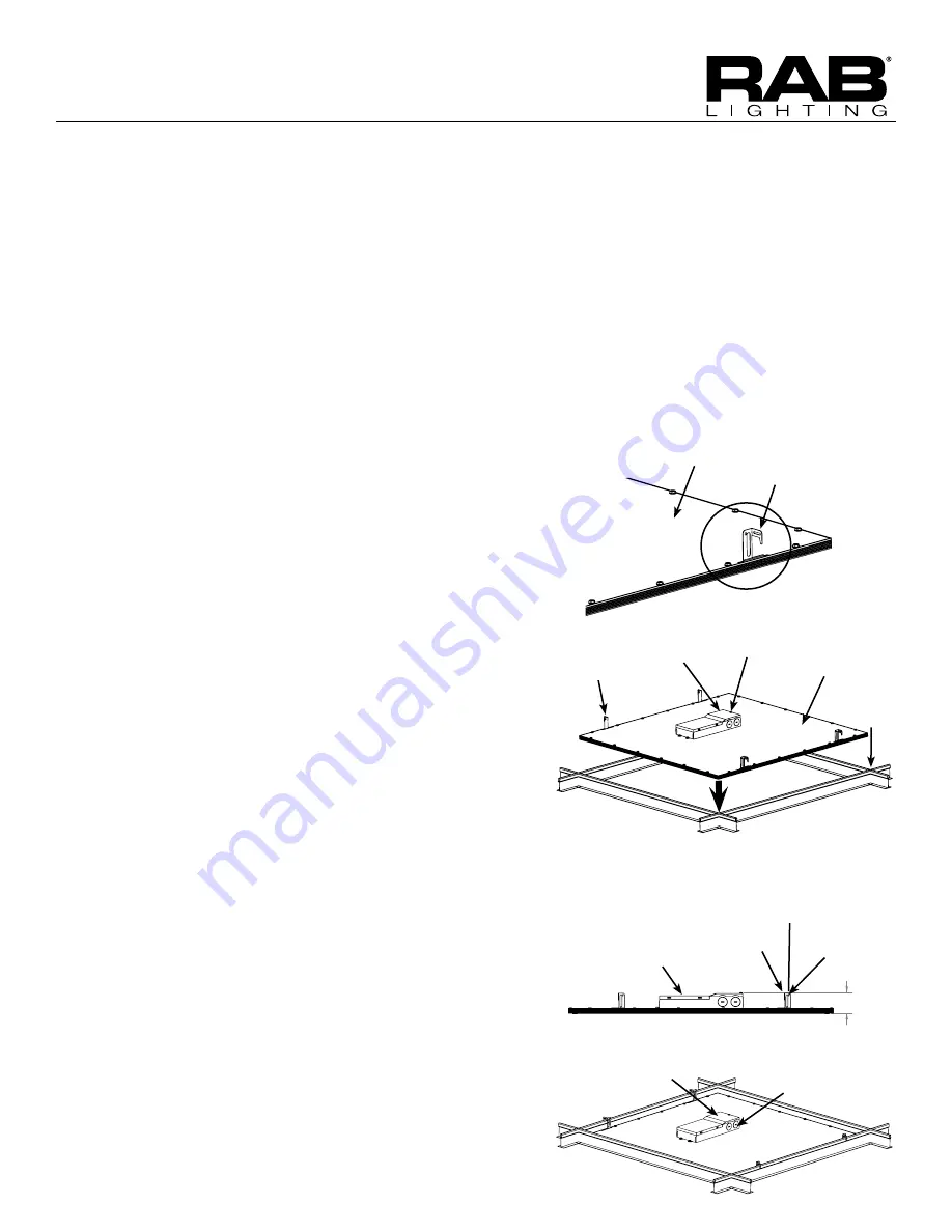
Fixture

Grid Clip (4)

Tee-Grid 

Bar

Access Plate Screw

Splice Box

 2 

Grid Clip 

Hole

Grid 

Clip

Power 

Feed

Fixture

Firmly bend Grid 

Clips up and out

RECESSED CEILING MOUNTING

The fixture is suitable only for INDOOR RECESSED CEILING 

application. Above ceiling access required.
To mount in an insulated or non-insulated ceiling - 9/16” or 

15/16” exposed Flat Tee Grid Ceiling follow the steps below. 
1.  Firmly bend the pre-installed Grid Clips (4) up and out 

as shown in Fig. 1. 

2.  Rotate and slide the Fixture as required to fit through 

the Tee-Grid Bar and place it as indicated by the 

directional arrow as shown in Fig. 2. Secure the Fixture 

to the  Tee-Grid Bar

3.  Support wires are required by Installation Codes. 

Support the Fixture to the building structure by 

Support Wires (supplied by others) through the Grid 

Clip Hole as shown in Fig. 3.

4.  Make sure that the orientation of the Splice Box and 

Access Plate faces an accessible tile to make electrical 

splices. 

5.  Loosen Access Plate Screw and remove the Access 

Plate. Knock out appropriate Conduit Knockouts 

on the Access Plate to route input conduit. Use 

appropriate conduit connectors as required by code   

(Fig. 4.).

6.  Connect wires as shown in wiring diagram. Push all 

wires back into the Splice Box. Use appropriate UL 

approved wire connectors as required by code to 

complete wiring. Terminal Block accepts input power 

wires of 16-18 AWG. If electrical supply wire is greater 

than 16 AWG the installer must connect using a              

16 AWG Pigtail (supplied). Be careful not to pinch wires. 

WARNING: To prevent wiring damage or abrasion, do 

not expose wiring to edges of sheet metal or other 

sharp objects. 

7.  Replace Access Plate and tighten Access Plate Screw.

Support Wire 

(supplied by 

others)

Fig. 2

Fig. 1

Fig. 3

Fig. 4

Summary of Contents for Lightcloud LCGATEWAY

Page 1: ...d out RECESSED CEILING MOUNTING The fixture is suitable only for INDOOR RECESSED CEILING application Above ceiling access required To mount in an insulated or non insulated ceiling 9 16 or 15 16 exposed Flat Tee Grid Ceiling follow the steps below 1 Firmly bend the pre installed Grid Clips 4 up and out as shown in Fig 1 2 Rotate and slide the Fixture as required to fit through the Tee Grid Bar and...

Page 2: ...Connect LINE supply lead to L marked on Terminal Block 2 Connect COMMON supply lead to N marked on Terminal Block 3 Connect the GROUND wire to pre installed Push in Connector 4 Connect DIM lead to DIM marked on Terminal Block 5 Connect DIM lead to DIM marked on Terminal Block Easy Installation Product Help Tech Help Line Call our experts 888 RAB 1000 2016 RAB LIGHTING Inc Northvale New Jersey 0764...

Page 3: ...anufactured in China 1 844 LIGHTCLOUD 1 844 544 4825 support lightcloud com Lightcloud is a commercial wireless lighting control system service It s powerful and flexible yet easy to use and install Learn more at lightcloud com 1 844 LIGHTCLOUD 1 844 544 4825 support lightcloud com WE RE HERE TO HELP ...

Page 4: ...sive infrared motion sensor that can switch and dim both hard wired circuits and remote circuits using Lightcloud Controllers Hello Product Features Advanced PIR Sensing Secure Cloud Control Configuration Retrofit Friendly Local Control Scheduling Astronomical Clock Power Monitoring 0 10V Dimming Patent Pending ...

Page 5: ...ING HUMIDITY 10 RH to 95 RH Non Condensing OVERALL DIMENSIONS 4 91 Diameter 1 61 Height WIRELESS RANGE Line of Sight 1000 feet Obstructions 100 feet Warranty is active as long as service plan is active Indoor Damp Location Lightcloud Ceiling Sensor Instruction Manual Wire Nuts x 4 x 2 What You Need Lightcloud Gateway A Lightcloud installation requires at least one Lightcloud Gateway to manage your...

Page 6: ...lling devices If there is a clear line of sight between two Lightcloud devices they can be placed up to 1000 feet apart If the two devices are separated by ordinary drywall construction try to keep them within 100 feet of each other Brick concrete and steel construction may require additional Lightcloud devices to go around the obstruction This product should only be installed by a qualified elect...

Page 7: ...ce to a row then write in additional information such as Zone name Panel Circuit Number and whether or not a zone uses dimming ZONE NAME PANEL CIRCUIT INSTALL AT A JUNCTION BOX INDOOR OUTDOOR The Ceiling Sensor can control other Lightcloud devices wirelessly If you don t need to hard wire a switched circuit to the Sensor no problem just tie the white red wire to neutral and cap off any unused wire...

Page 8: ...ity Confirm Status Indicator is solid green If it is not make sure your device is within range of another Lightcloud AC powered device To add new devices to your Lightcloud network call RAB at 1 844 LIGHTCLOUD or email us at support lightcloud com STATUS INDICATOR ...

Page 9: ...to sensor by pushing up and twisting to the right clockwise 7 Commission Configure Your Devices All Lightcloud products can be commissioned and configured by Logging on to lightcloud com Calling RAB at 1 844 LIGHTCLOUD Emailing us at support lightcloud com ...

Page 10: ...CATOR After the Device Button has been pressed this indicator illuminates when the device receives a message and indicates the strength of the signal 3 Best Signal 2 Acceptable Signal 1 Unacceptable Signal Consult the Finding a Location section for more information DEVICE BUTTON Press once to highlight this device in the Lightcloud Application pressing once also enables display of the Signal Indic...

Page 11: ...l be used via Lightcloud Automations to control other devices CONTROLLER MODE In Controller Mode the attached circuit is controllable as an independent zone in the Lightcloud application Motion detection and timeout can still be used via Lightcloud Automations to control other devices RANGE TEST MODE When Range Test Mode is activated via the Lightcloud application the timeout period is shortened s...

Page 12: ...mation This device complies with Part 15 of the FCC Rules Operation is subject to the following two conditions 1 This device may not cause harmful interference and 2 This device must accept any interference received including interference that may cause undesired operation Note This device has been tested and found to comply with the limits for Class B digital devices pursuant to Part 15 Subpart B...

Page 13: ...e NJ 07647 Custom manufactured in China 1 844 LIGHTCLOUD 1 844 544 4825 support lightcloud com Lightcloud is a commercial wireless lighting control system service It s powerful and flexible yet easy to use and install Learn more at lightcloud com ...

Page 14: ...Welcome LCCONTROL20 D10 Controller 1 844 LIGHTCLOUD 1 844 544 4825 support lightcloud com WE RE HERE TO HELP ...

Page 15: ......

Page 16: ......

Page 17: ...ctronic 20A FLA 60 LRA 2HP 120VAC 15A Tungsten 1HP OPERATING TEMPERATURE 40ºC to 40ºC OVERALL DIMENSIONS 1 55 diameter 5 75 length 1 2 NPT Mount Male 16AWG pigtails WIRELESS RANGE Warranty is active as long as service plan is active Class 2 IP66 Rated Indoor and Outdoor Rated Wet and Damp Location Plenum Rated Lightcloud Controller Instruction Manual Wire Nuts NPT Nut O ring x 4 x 2 Line of Sight ...

Page 18: ...What You Need Lightcloud Gateway A Lightcloud installation requires at least one Lightcloud Gateway to manage your devices 1 844 LIGHTCLOUD or 1 844 544 4825 support lightcloud com WE RE HERE TO HELP ...

Page 19: ... neutral line for the load being switched This enables power measurement See the Power Measurement section under Functionality for more information BLACK WHITE RED 0 10V DIMMING Panel Controller Lightcloud Load BLACK HOT WHITE NEUTRAL WHITE BLACK RED WHITE PURPLE GRAY PURPLE GRAY ...

Page 20: ...e placed up to 1000 feet apart If the two devices are separated by ordinary drywall construction try to keep them within 100 ft of each other Brick concrete and steel construction may require additional Lightcloud devices to go around the obstruction Lightcloud Gateway 100 ft Add an additional Lightcloud Device to extend network range around corners BRICK CONCRETE OR METAL WALL DRY WALL OR SIMIL A...

Page 21: ...have an equal or better insulation rating You may need to complete your low voltage wiring in another enclosure or use a partition 0 10V is a common method of low voltage control of dimmable drivers and ballasts Purple 0 10V positive Gray 0 10V common 2a Install at a Junction Box Indoor Outdoor Controller Lightcloud RED WHITE WHITE BLACK GRAY PURPLE WHITE RED To Load To Panel To Driver Ballast ...

Page 22: ... or Trough Space and code allowing you may install Lightcloud devices directly in your breaker box or lighting panel Alternatively break out lighting circuits and install Lightcloud devices in a separate trough WHITE BLACK ...

Page 23: ...o a building manager Attach the Device Identification stickers included with each device to a row then write in additional information such as Zone name Panel Circuit Number and whether or not a zone uses dimming Your Site Name ZONE NAME PANEL CIRCUIT DIMMING Front Desk 2 DEVICE ID 1 1 2 3 To add new devices to your Lightcloud network call RAB at 1 844 LIGHTCLOUD or email us at support lightcloud ...

Page 24: ... 5 STATUS INDICATOR SIGNAL INDICATOR Confirm Device Connectivity Illuminated when device is powered Press once to highlight this device in the Lightcloud Application Press twice and hold to set dim level Press twice to toggle circuit on and off Press and hold for 10 seconds to remove this device from a Lightcloud network Blinks when device is indicated from the Lightcloud Application DEVICE IDENTI...

Page 25: ...le zone TRIGGER Detect when an attached circuit is open or closed For example you could attach the Controller in Trigger mode to an existing occupancy sensor to allow your Lightcloud system to react to the sensor GRAY Controller Lightcloud Load Existing Occupancy Sensor WHITE WHITE WHITE BLACK BLACK BLACK RED PURPLE RED BLACK WHITE WHITE RED 1 844 LIGHTCLOUD or 1 844 544 4825 support lightcloud co...

Page 26: ...ze this function the neutral wire of the load must be connected to the white red sense wire If the Switched Neutral line cannot be used it should be tied to the regular neutral wires i e all neutral wires joined POWER LOSS DETECTION If mains power to the Controller is lost the device will detect this and alert the Lightcloud application EMERGENCY DEFAULT If communication is lost the Controller may...

Page 27: ...will not occur in a particular installation If this equipment does cause harmful interference to radio or television reception which can be determined by turning the equipment off and on the user is encouraged to try and correct the interference by one or more of the following measures Reorient or relocate the receiving antenna Increase the separation between the equipment and receiver Connect the...

Page 28: ......

Page 29: ...ctured in China 1 844 LIGHTCLOUD 1 844 544 4825 support lightcloud com Lightcloud is a commercial wireless lighting control system service It s powerful and flexible yet easy to use and install Learn more at lightcloud com 1 844 LIGHTCLOUD 1 844 544 4825 support lightcloud com WE RE HERE TO HELP ...

Page 30: ...ot installed and used in accordance with the instruction manual may cause harmful interference to radio communications However there is no guarantee that interference will not occur in a particular installation If this equipment does cause harmful interference to radio or television reception which can be determined by turning the equipment off and on the user is encouraged to try and correct the ...

Page 31: ...ud Daylight Instruction Manual Mounting Screws Straight Angled Mounting Brackets Power Supply for Setup USB Cable for Setup What You Need Lightcloud Gateway A Lightcloud installation requires at least one Lightcloud Gateway to manage your devices The Daylight is designed to remotely control one or more Lightcloud devices that are capable of switching or dimming such as the Lightcloud Controller or...

Page 32: ...work plug it in with the included Micro USB power adapter The white Power Indicator will come on and the Device Status Indicator will blink red every 10 seconds until it is joined to your network For setup purposes you can plug the device in anywhere that s convenient but please stay near the location where it will be permanently installed in order to ensure continued network connectivity Once set...

Page 33: ...ble if there s enough of it 3 Find a Suitable Location Example of ideal placements 3a A skylight is a great location for the Lightcloud Daylight Be aware of where shadows will land throughout the day and position the device where it will receive the most direct sunlight 3b NOTE Remember south facing surfaces usually receive more direct sunlight than north facing surfaces SKYLIGHT ...

Page 34: ...ure it ends up in direct sunlight as much as possible 3d DIRECT SUNLIGHT Use angled bracket to get more direct sunlight DIRECT SUNLIGHT May need to use an extension to obtain direct sunlight CEILING WINDOW The Daylight must be within range of a Lightcloud device or Gateway See Finding a Location The Daylight will not act as a repeater to extend the range of your Lightcloud network If you need to e...

Page 35: ...pplication will show the last measured light level so you can configure actions to take at different levels Or simply call or email us 5 Configure 1 844 LIGHTCLOUD 1 844 544 4825 support lightcloud com Screw the straight or angled mounting bracket to the mounting surface 4a Snap the Daylight onto the mounting bracket 4b ...

Page 36: ...SB powered Force device to leave current Lightcloud network Hold for 10 seconds while connecting USB power Reset to factory defaults and leave current network DAYLIGHT HARVESTING Daylight Harvesting is the use of daylight to offset the use of electric lighting to light a space If there s enough daylight in a space the Lightcloud Daylight can make sure the lights are turned down or off and turn the...

Page 37: ...O HELP RAB Lighting Inc 170 Ludlow Avenue Northvale NJ 07647 Custom manufactured in China 1 844 LIGHTCLOUD 1 844 544 4825 Lightcloud is a commercial wireless lighting control system service It s powerful and flexible yet easy to use and install Learn more at lightcloud com ...

Page 38: ...htcloud Dimmer is an in wall switch that connects wirelessly to a Lightcloud Controller to provide switching dimming and scene control Hello Product Features Wireless Control Configuration Zone Switching Dimming Dim Level Indicator Scene Selection Nightlight ...

Page 39: ... 1 77 W x 2 7 H x 1 49 D Faceplate 2 94 W x 4 69 H x 0 06 D Faceplace Bracket 2 8 W x 4 55 H x 0 13 D 18AWG grounding terminals supporting up to 12AWG wire WIRELESS RANGE Line of Sight 1000 feet Obstructions 100 feet Contents Dimmer Faceplate Faceplate Bracket Instruction Manual 2x 6 32 1 2 Screws 2x 6 32 5 16 Screws ...

Page 40: ...hould only be installed by a qualified electrician and in compliance with local and national electrical codes This product should only be installed in a UL approved single gang wall box enclosure Indoor use only What You Need A Lightcloud Gateway A Ceiling Sensor Or similar actuator 1 844 LIGHTCLOUD or 1 844 544 4825 WE RE HERE TO HELP ...

Page 41: ...nother device to the network If there is a clear line of sight between two Lightcloud devices they can be placed up to 1000 feet apart If the two devices are separated by ordinary drywall construction try to keep them within 100 feet of each other Brick concrete and steel construction may require additional AC powered Lightcloud devices to go around the obstruction See the Deployment section of yo...

Page 42: ...rew the line black and neutral white wires into the labeled connectors on the back of the Dimmer Connect the ground wire green 2b Use the two 6 32 1 2 Phillips round head screws to secure the Dimmer to the junction box Make sure the arrow labeled TOP is pointing up ...

Page 43: ...he faceplate onto the faceplate bracket 2c Use the two 6 32 5 16 Phillips flat head screws provided to secure the faceplate bracket to the Dimmer Setup Installation cont d 2 Install the Lightcloud Dimmer cont d ...

Page 44: ... dimming DEVICE IDs ZONE NAME PANEL CIRCUIT 3 Labeling your device 4 Power up To add your Lightcloud Dimmer to your system enable Setup Mode via the Lightcloud application or call RAB at 1 844 544 4825 When the Dimmer powers up it will automatically try to join and keep trying until it is able to join If you are installing multiple devices you may wait until they are all installed to enable Setup ...

Page 45: ...orce device to leave current Lightcloud network DIM LEVEL INDICATOR Displays current dim level Zone mode NIGHTLIGHT White Lit when zone is off so you can find the dimmer SIGNAL STRENGTH INDICATOR Indicates strength of the connection to next Lightcloud Device NETWORK INDICATOR Solid green Connected to a Lightcloud network Blinking red Not connected to a Lightcloud network The network and signal str...

Page 46: ...been tested and found to comply with the limits for Class B digital devices pursuant to Part 15 Subpart B of the FCC rules These limits are designed to provide reasonable protection against harmful interference in a residential environment This equipment generates uses and can radiate radio frequency energy and if not installed and used in accordance with the instruction manual may cause harmful i...

Page 47: ...Manual ...

Page 48: ... offer recycling or collection of rechargeable batteries contact your local government for disposal practices in your area DISCONNECT An external readily accessible disconnect device such as a circuit breaker is required Contents Introduction System Overview Lightcloud Gateway Lightcloud Devices Finding a Suitable Location Best Practices Best Practices Getting Started Installation Lightcloud Gatew...

Page 49: ...e charge of your lighting from sensing to dimming schedules to scenes and everything in between Control and configure your system remotely using the Lightcloud Application or call RAB to have our experts set up your system just how you need it Welcome to lighting control that just works 5 ...

Page 50: ...l configuration at control lightcloud com Device commissioning Free support Telephone concierge Energy monitoring 6 Lightcloud Gateway The Gateway connects your system to our secure private server via a cellular signal so you don t have to worry about providing your own internet connection With the Gateway powered and connected your Lightcloud site is at your command with the Lightcloud Applicatio...

Page 51: ...sensing Switches up to 15A and provides 0 10V dimming Lightcloud Dimmer The Wall Dimmer puts advanced control at your fingertip Configure via the Lightcloud App to switch dim a zone or change scenes Learn more about Lightcloud Devices at lightcloud com Lightcloud Devices Finding a Suitable Location The Gateway should be installed in a dry or non condensing damp environment only Use these guideline...

Page 52: ...ge around corners BRICK CONCRETE OR METAL WALL DRY WALL OR SIMIL AR M E TA L CO N C R E T E B R I C K PROBLEM MATERIALS Large amounts of metal concrete and brick are bad news for radio signals in some cases you ll have to go around these obstacles with additional AC powered Lightcloud devices Best Practices M I C R OWAV E S E L E VATO R M EC H A N I C A L R O O M S A M P L I FI E R S A N T E N N A...

Page 53: ...SIGNAL STRENGTH SYSTEM STATUS LED Indicators POWER Green Fully powered CELLUL AR Off No or poor cellular signal You must move the Gate way to a location with better cellular signal Solid Yellow Adequate cellular signal This signal strength works for most applications but if possible move to a location with better signal Solid Green Good cellular signal SYSTEM STATUS Blinking Yellow Initializing So...

Page 54: ...ignal Check your phone s signal for reference NOTE Locations with significant concrete and brick construction or underground locations are not recommended Do not install inside metal enclosures 1 2 3 OFF OFF WARNING STEP ONE STEP TWO STEP THREE 3 14 5 Mount the Gateway to the installation surface using size 10 screws appropriate for the surface material For direct installation onto an external jun...

Page 55: ...ce Table is essential for referencing during setup or for troubleshooting don t forget it Two copies are provided one to keep near your Gateway and one for the building owner or facility manager to file PWR ENGY if a zone uses the Controller s integrated power monitoring place a checkmark DIM if a zone uses the Controller s 0 10V dimming wires place a checkmark here Lightcloud Devices Lightcloud d...

Page 56: ...e designed to provide reasonable protection against harmful interference in a residential environment This equipment generates uses and can radiate radio frequency energy and if not installed and used in accordance with the instruction manual may cause harmful interference to radio communications However there is no guarantee that interference will not occur in a particular installation If this eq...

Page 57: ......

Page 58: ...ured in China 1 844 LIGHTCLOUD 1 844 544 4825 support lightcloud com Lightcloud is a commercial wireless lighting control system service It s powerful and flexible yet easy to use and install Learn more at lightcloud com 1 844 LIGHTCLOUD 1 844 544 4825 support lightcloud com WE RE HERE TO HELP ...

Page 59: ...et that gives users a convenient and customizable interface for controlling a Lightcloud site Hello Product Features AC powered for permanent installation Customizable zone and scene control Direct local control for minimum latency Easy setup from your computer or mobile device or just call RAB Patent Pending ...

Page 60: ...ANGE Line of Sight 1000 feet Obstructions 100 feet Indoor Rated Lightcloud Touch Instruction Manual Six 6 18 x 1 Drywall Screws What You Need Lightcloud Gateway A Lightcloud installation requires at least one Lightcloud Gateway to manage your devices 1 844 LIGHTCLOUD 1 844 544 4825 support lightcloud com WE RE HERE TO HELP Lightcloud Controller Or similar Lightcloud actuation device ...

Page 61: ...nect devices such as the Dimmer to the Gateway Unlike a WiFi router each Lightcloud device may connect another device to the network If there is a clear line of sight between two Lightcloud devices they can be placed up to 1000 feet apart If the two devices are separated by ordinary drywall construction try to keep them within 100 feet of each other Brick concrete and steel construction may requir...

Page 62: ... your panel and one to hand off to a building manager Attach the Device Identification stickers included with each device to a row then write in additional information such as Zone name Panel Circuit Number and whether or not a zone uses dimming 4 Enabling your device DEVICE IDs ZONE NAME PANEL CIRCUIT 4a Turn the Touch on by holding the power button on top ...

Page 63: ...cont d 4 Enabling your device cont d 4b Call RAB at 1 844 LIGHTCLOUD or email us at support lightcloud com to add the Touch to your Lightcloud network 4c Once the Touch has joined your network you ll see the screen below ...

Page 64: ... com Calling RAB at 1 844 LIGHTCLOUD Emailing us at support lightcloud com Configure 1 844 LIGHTCLOUD 1 844 544 4825 support lightcloud com 1 Configuring the Touch by calling or emailing RAB 2 Configuring the Touch using the web mobile application Navigate to https control lightcloud com and log in 2a ...

Page 65: ...ty cont d 2 Configuring the Touch using the web mobile application cont d Click the menu icon in the top left 2b Navigate to your Site then click Devices 2c Find your Touch device in the Device List on the left 2d ...

Page 66: ...g the web mobile application cont d Within a few seconds the tablet UI refreshes to reflect our changes 2f Click the icon to add zone and or scene controls to your Touch 2e In this example we ve configured our Touch to control two zones and one scene ...

Page 67: ... will not occur in a particular installation If this equipment does cause harmful interference to radio or television reception which can be determined by turning the equipment off and on the user is encouraged to try and correct the interference by one or more of the following measures Reorient or relocate the receiving antenna Increase the separation between the equipment and receiver Connect th...

Reviews: