2
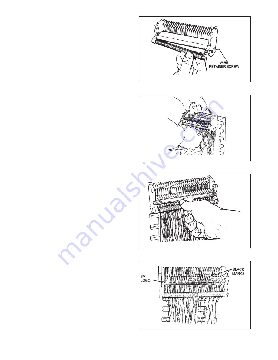
c. Check that Splicing Head wire retainer spring is set
to proper gauge. To change, loosen wire retainer
screw and turn spring assembly to proper size as
stated on spring face plate. See Figure 55. Springs
are color coded: RED-.5 mm (24 Ga.) Pulp/paper and
all .4 mm (26 Ga.) BLACK-.5 mm (24 Ga.) PIC and
all .6-.8 mm (22 Ga.)
d. Select either 4010E Feeder Module (green cover) or
4011 E Distribution Module (blue cover).
e. Place Module Base into leaf springs of Splicing Head
so alignment holes are towards head wire guides and
cut-off blades are towards craftsman.
f. On cables entering from top, train first binder group
under the temporary tie and over the head. On cables
entering from bottom, bring first binder group up
the channel of the frame through the Splice Head
Adapter Legs and over top of Splicing Head. See
Figure 56.
g. Pairs go to the right of the color-coded wire guides.
Use a thumb and forefinger of each hand to guide
wire pairs over pair splitter. Place TIP wire to the
left, RING wire to the right. Take up slack by pulling
wires firmly into wire channels on Base and into the
wire retainer spring. Follow color code.
h. When Base is filled, check wiring order with the
4052 Check Comb. See Figure 57.
i. Place Module Body/Cover assembly into leaf springs
of Splicing Head, with 3M logo in lower left hand
corner and black marks toward Head wire guides. See
Figure 58.
Figure 55.
Figure 56.
Figure 57.
Figure 58.
Summary of Contents for MS2 4000 Series
Page 2: ......
Page 5: ... ...
Page 21: ...21 Figure 46 Figure 47 ...
Page 36: ...36 D Supply Information ...
Page 37: ...37 ...
Page 39: ...39 ...


