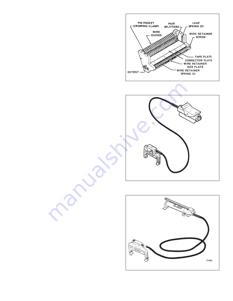
A. Splicing Head Detail (See Figure 97).
Wire guides, pair splitters, and retainer springs are coated
with an electrical insulation. Tape plate is plastic.
B. MS
2
Air/Hydraulic Crimping Unit (See Figure 98).
1. Description-Pump can be operated either by foot or
hand. An air cylinder or compressor with an output
pressure of 6.3-7.0 Kg/cm2 (90-100 Psi may be used
as source. It is recommended that this pressure be held
as close to the upper end as possible to provide a faster
crimping action.
The air/hydraulic pump is factory adjusted to a pressure cut-
off of 309 Kg/cm
2
(4400 psi) (nominal). A by-pass valve
opens when cut-off pressure is reached; crimping clamp will
hold until released.
The air supply fitting on pump is air valve Schrader Catalog
No. 645-A6. It mates with:
a. Chuck, Air Snap-On Schrader No. 5499.
b. Chuck, Clip Schrader No. 6529.
2. Bleeding Instructions (if crimping bar does not come
down)-To bleed if air-bound, place clamp lower than
pump and tilt output hose of pump up. Press pedal until
clamp resumes normal operation.
3. Connecting Hose-1.8 m X 6.4 mm (6' X 1/4") rubber
hydraulic hose (steel reinforced) Male 1 /4" - 18 NPT
fitting on each end with spring guards.
C. MS
2
4031 Hand/Hydraulic Crlmping Unit (See
Figure 99)
1. Pressure cut-off is set at factory to 309 Kg/cm
2
(4400
psi) (nominal). By-pass valve opens when cutoff
pressure is reached; crimping clamp will hold until
released.
2. Bleeding Instructions (if crimping bar does not come
down)-To bleed if air-bound, place clamp lower than
pump and tilt output hose of pump down. Actuate
handle until clamp resumes normal operation.
3. Connecting Hose-1.8 m X 6.4 mm (6' X 1/4") rubber
hydraulic hose (steel reinforced) Male 1 /4" - 18 NPT
fitting on each end with spring guards.
Figure 97.
Figure 98.
Figure 99.
Summary of Contents for MS2 4000 Series
Page 2: ......
Page 5: ... ...
Page 21: ...21 Figure 46 Figure 47 ...
Page 36: ...36 D Supply Information ...
Page 37: ...37 ...
Page 39: ...39 ...


