background image

2.  

3.  
4.  

5.  

Power up printer as described in 

.  Establish a network connection between printer and PC.

7.1 Power on Printer

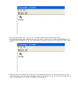
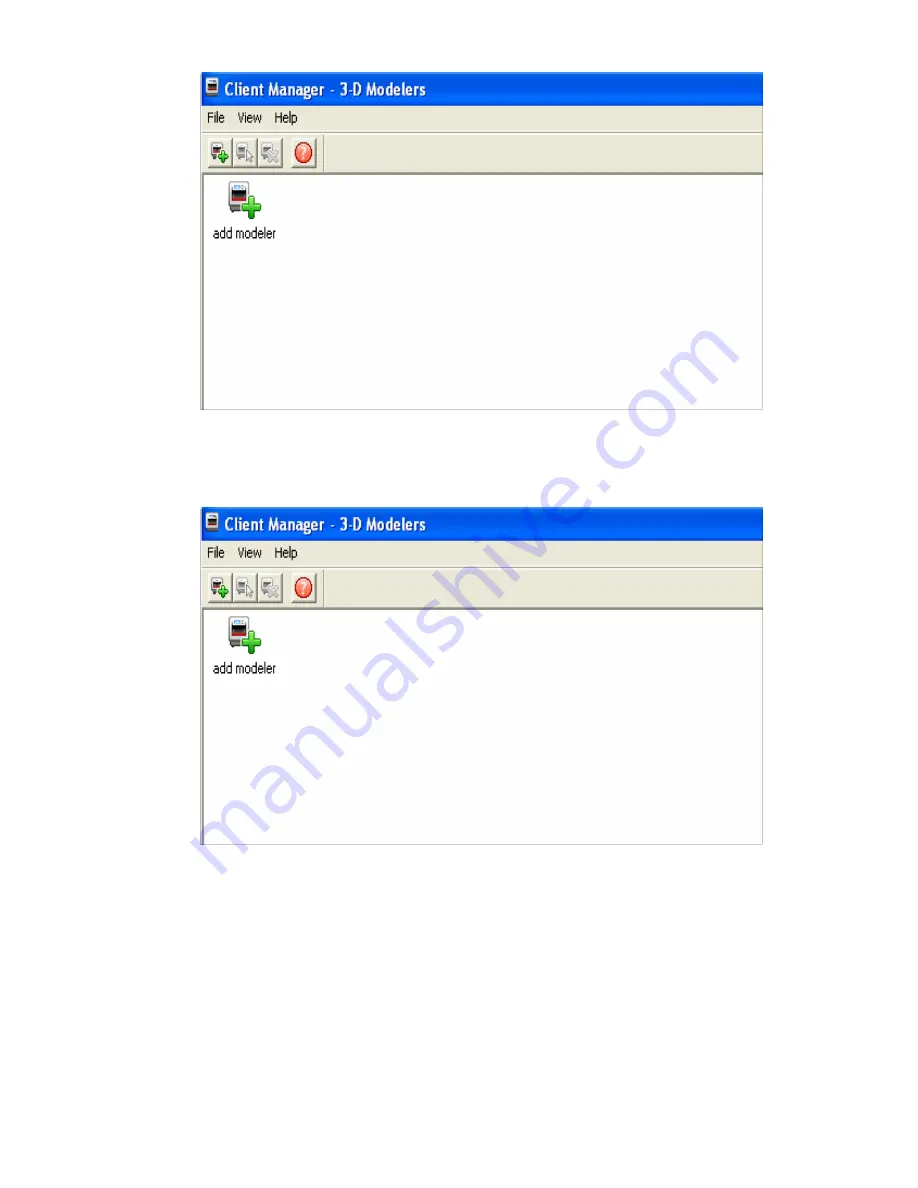
Build jobs can only be submitted to printers that have icons in the window. To create an icon for a printer, click 

 icon (or

Add printer

choose 

), the "Add Printer" window appears, prompting to choose the printer's IP address from list of available

File > Add 3-D modeler

printers. 

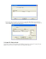
Select the IP address for desired printer, click OK *NOTE: The IP address is located in the . The client software prompts for a printer
name. After entering a name, an icon for the printer appears in the 3-D Printers window. Once an icon exists, click on it to add files for a
build job, preview build job, summit a build job, or manage a build job in progress. 

Summary of Contents for ProJet 5000

Page 1: ...ubmit Test Build 24 1 7 6 7 6 Build Demo 25 1 8 08 0 Operations 25 1 8 1 8 1 Print Preview Overview 26 1 8 1 1 8 1 1 Add Part 27 1 8 1 2 8 1 2 Part Selections Translation Rotation 28 1 8 1 3 8 1 3 Submit Job 29 1 8 1 4 8 1 4 Trackball View 29 1 8 1 5 8 1 5 Triangle Selection 30 1 8 1 6 Align Parts Facings 31 1 8 1 7 Auto Part Placement 32 1 8 1 8 Back View 33 1 8 1 9 Bottom View 34 1 8 1 10 Boundi...

Page 2: ...Lines 83 1 11 11 0 Troubleshooting 85 1 11 1 11 1 Communication Errors 85 1 11 2 11 2 Head Maintenance Station Errors 85 1 11 3 11 3 Material Feed and Waste System Errors 86 1 11 4 11 4 Material Quality Guarantee Errors 86 1 11 5 11 5 Material Waste Errors 86 1 11 6 11 6 Motion System Errors 87 1 11 7 11 7 UV Subsystem Errors 87 1 11 8 11 8 Vacuum Regulator Errors 87 1 11 9 11 9 Power Outage 87 1 ...

Page 3: ...on 4 6 Spilled VisiJet Material 4 7 Waste Removal 4 8 Material Storage 05 0 System Requirements 06 0 Familiarization 6 1 System Functions 07 0 Printer Setup 7 1 Power on Printer 7 2 Install Remove Material Bottles and Build Platform 7 2 1 MDM Installation 7 3 Install and Run ProJet 3 D Modeling Client Software 7 4 Create STL File s to Build 7 5 Submit Test Build 7 6 Build Demo 08 0 Operations 8 1 ...

Page 4: ... 3 Abort Build Job 8 4 4 Repeat Build Job 8 5 Printer Status 8 6 Empty Waste Drawer 8 7 Shutdown Printer 8 8 Remove Part from Build Platform 8 9 Shrink Compensation for VisiJet MX Part Material 09 0 Maintenance 9 1 Cleaning Printer Surfaces 9 2 Cleaning the Waste Drawer 9 3 Preventive Maintenance 9 4 Return Printer for Repair 9 5 UV LED Cleaning Procedure 9 5 1 UVLED Board Removal Procedure 9 6 Cl...

Page 5: ...ements 17 0 Glossary of Terms 18 0 Index 01 0 Introduction Thank you for purchasing a ProJet 3 D Printer System We pride ourselves in our ability to offer customers three dimensional modeling solutions The 3D Systems team is confident your system will provide many years of service 1 1 About this Guide 1 2 Copyright 1 3 Useful Documents 1 4 What s Inside 1 5 Features 1 6 Packaging 1 1 About this Gu...

Page 6: ...perating conditions and 3D Systems undertakes no responsibility in these areas IN NO EVENT WILL 3D Systems BE RESPONSIBLE FOR DAMAGES OF ANY NATURE INCLUDING SPECIAL OR CONSEQUENTIAL DAMAGES RESULTING FROM THE USE OF OR RELIANCE UPON THIS INFORMATION THE CUSTOMER ASSUMES ALL RISK RESULTING FROM THE USE OF THIS INFORMATION Customer use of the materials that follow is an acknowledgment of its agreem...

Page 7: ...nload build parts and disposing waste material Error Messages Defines error messages you may see on the printer s LCD and provide the actions to take to correct the problem Finishing Provides information on finishing models Maintenance List printer maintenance procedures which must be done to ensure high part yield and low printer down time Semi annual preventive maintenance requires a certified 3...

Page 8: ...for investment casting of fine detailed and high precision components Part Stacking and Nesting The new ProJet 3 D Production System features part stacking and nesting capability in both build modes Stacking The user can now utilize the entire build volume by stacking parts vertically in the z direction to fill up the entire build envelop with parts The user can control the space between layers to...

Page 9: ...orm 1 6 Packaging Packaging Do not damage or discard any packaging materials or crate If the printer needs to be returned to the manufacturer it should be shipped in it s original packaging and crate If other method of packaging is used the customer will be responsible for any shipping damages that may occur Only Certified Qualifed Service Personnel can install the 3 D printer 02 0 Safety Symbols ...

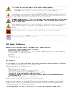
Page 10: ...e The safety program should Label and point out hazardous equipment materials and procedures Explain what to do in case of an emergency Provide information about hazards of equipment and materials in the form of Material Safety Data Sheets MSDSs The MSDSs are provided with all materials supplied by 3D Systems 3 1 General 3 2 Electrical 3 3 Ultraviolet UV Light 3 1 General The printer is designed w...

Page 11: ...is open When closed the chamber door keeps UV radiation from escaping The chamber door remains locked if build job is paused 04 0 Part Material Safety Users of the printer should be informed of potential hazards of part material prior to working with a printer or performing duties which may result in exposure to uncured part material such as removal and disposal of empty material bottles and or wa...

Page 12: ...cured VisiJet part material is a sensitizer Skin or eye irritation could occur when exposed to the chemical composition of the material Uncured material is a sensitizer and can cause allergic reactions if contacts skin without protective gloves Refer to for more information To avoid personal protection equipment sensitization do not allow uncured material to contact skin Consult the MSDS for speci...

Page 13: ... material is observed on the part or platform after build this is an abnormal condition and is an indication the printer requires servicing by 3D Systems Assume any liquid or paste like material is part material Do not directly touch uncured part material without protective gloves Discontinue use of the printer pending service by a 3D Systems Technical Support Representative or your servicing rese...

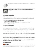
Page 14: ...to be uncured part material and handle accordingly with the recommended personal protective equipment Promptly clean up spilled material dispose of clean up materials and waste material per local regulatory requirements Discontinue use of the printer and contact 3D Systems for a service visit to determine and repair the source of leakage Technical Support Small spills of uncured liquid part materi...

Page 15: ...y reversing the previous process Close waste drawer after waste bag is installed 4 8 Material Storage PART MATERIAL SUPPORT MATERIAL VisiJet MX VisiJet S300 1 yr Shelf life 2 yr Shelf life Cool dry area with adequate ventilation Climate Cool dry area with adequate ventilation Climate 60 F 16 C to 80 F 27 C Temperature Range 60 F 16 C to 80 F 27 C Temperature Range 95 F 35 C Maximum Storage Temp 95...

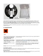
Page 16: ...MDM and are still warm it must be stored with the cap vented If the warm bottle is not vented the wax will contract during cooling and the bottle s bottom may become flat which will prevent reengagement in the MDM Support material bottles must be loaded in the side material delivery module The part material bottles must be loaded in the material left right delivery module Before loading material b...

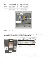
Page 17: ...pe system The solid imaging printer produces plastic prototype parts from 3D solid Computer Aided Design CAD and through the ProJet Client Software The parts are generated in a rapid prototyping RP environment The primary features are the operator panel build chamber material delivery systems and waste drawer The three dimensional solid parts built by the printer consist of two materials support m...

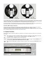
Page 18: ...esides above the bag to cure the top layer of material in the bag After the build is complete the platform and the part are removed A secondary operation known as finishing is required to provide a finish clean part For cleaning and finishing instructions refer to the VisiJet Material Handling 6 1 System Functions The instructions use special text formats to highlight menu commands keys on the key...

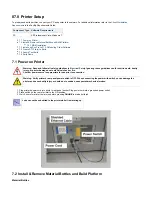
Page 19: ...s in Electrical Safety Ignoring these guidelines could result in death bodily injury or printer damage due to electrical shock or fire Confirm power source is appropriate for use prior to connection Warning Verify printer s rear panel power switch is OFF When connecting the power with switch on can damage the printer and cause bodily injury or death due to sudden unexpected mechanical motion Plug ...

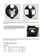
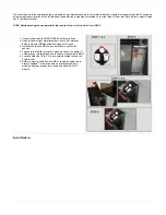
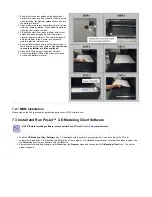
Page 20: ...bottles and the MSDS SDS Sheet from cartons Open left and or right material delivery doors Pull material delivery module MDM handle down and out to open Install bottle into the MDM press bottle down until a click sounds To ensure that bottle is locked in place gently pull on bottle If bottle is loose press bottle down to ensure it is secured in MDM Loosen bottle cap 1 2 to 3 4 turn counterclockwis...

Page 21: ...ot to drop the platform or hit the printhead Close build chamber door and press ONLINE To remove platform lift from the sides pull up and out from the platform elevator 7 2 1 MDM Installation Please click on the link to access the installation instructions MDM Installation pdf 7 3 Install and Run ProJet 3 D Modeling Client Software NOTE Before installing software ensure network and PC meet require...

Page 22: ...nter window appears prompting to choose the printer s IP address from list of available File Add 3 D modeler printers Select the IP address for desired printer click OK NOTE The IP address is located in the The client software prompts for a printer name After entering a name an icon for the printer appears in the 3 D Printers window Once an icon exists click on it to add files for a build job prev...

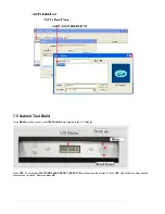
Page 23: ...red lightning bolt your PC is not communicating with the printer Jobs cannot be submitted to the printer until communication is restored 7 4 Create STL File s to Build The printer builds 3 D models from files using industry standard ereo ithography format Most popular 3 D modeling CAD software STL ST L packages can save files in STL format Sample STL files are in the 3 D Modeling Client Samples fo...

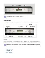
Page 24: ...l up or down until is high lighted in the LCD Display MENU TEST BUILD Press The message scrolls across the display Press if the platform is clear and the YES PLATFORM CLEAR DOOR CLOSED Y N YES chamber door is closed otherwise press NO ...

Page 25: ...g and managing jobs through the printer s operator panel menu and 3 D Modeling Client Software In addition this section describes how to remove the build platform how to empty the waste drawer and how to shut down the printer Make certain the printer is Off Line during the job submittal process Place the printer on line after the job is submitted 8 1 Print Preview Overview 8 2 Save a Build Job 8 3...

Page 26: ...functionality of the print preview icons along with their individual video clip Preview a build job before submitting Preview jobs before submitting them to the printer Click button on the Client s Submit dialog box At least one part must be added for build in the Submit dialog box before able Preview to preview ...

Page 27: ...ubmit Job 8 1 4 Trackball View 8 1 5 Triangle Selection Align Parts Facings Auto Part Placement Back View Bottom View Bounding Box Display Copy Delete De Select all De Select all Triangles Display Support Creation Surface Estimate Build Time Front View Help Topics Isometric View Mirror Right View Rotate Scale Scale inch to mm Scale mm to inch Select all Selected Part Information Selected Parts Sha...

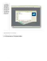
Page 28: ... The or CTL File system displays a file browser dialog box which you can use to select one or more parts Select open on the dialog box to add part to the print preview platform Click here to return to Print Preview Browser 8 1 2 Part Selections Translation Rotation ...

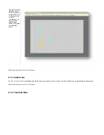
Page 29: ...t be viewed in top bottom left or right to manipulate them Click here to return to Print Preview Browser 8 1 3 Submit Job See Submit Job section to understand how this function is used to submit a job Once a job is submitted it can be manipulated in print preview Click here to return to Print Preview Browser 8 1 4 Trackball View ...

Page 30: ...area Normal dragging with the left mouse button pressed down rotates the viewing area When using the right mouse button the build envelope can be dragged around within the viewing area Click here to return to Print Preview Browser 8 1 5 Triangle Selection ...

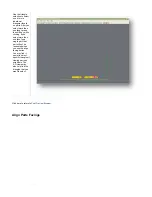
Page 31: ...e clicking If you select more than one facet on a single part that part will not be reoriented when you use the align facing button You may find it easier to select specific triangles if viewing parts as wireframe The 2 D views may also help find the triangles that you want to select Click here to return to Print Preview Browser Align Parts Facings ...

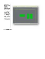
Page 32: ...the X Z axis or the Y Z axis Select a triangle using the triangle selection tool the align facing buttons become enable Click the align part icons to rotate the part until the selected triangle faces the selected direction Triangles can be selected on several parts before clicking an align Parts Facing icons so that all parts can be aligned together Auto Part Placement ...

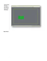
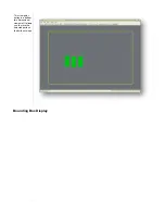
Page 33: ...This tool arranges parts for optimum build speed Select the parts and click on auto place The parts will automatically arrange in the build envelope Back View ...

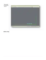
Page 34: ...This view point button is a back two dimensional viewpoint Bottom View ...

Page 35: ...This view point button is a bottom two dimensional viewpoint It allows you to move the selected parts on the build envelope Bounding Box Display ...

Page 36: ...A bounding box for a set of objects is a cuboid that completely contains the set Copy ...

Page 37: ...he number of copies and the distance between them Enter the number of copies and distance click Apply to generate the copies Delete To delete a part parts from the platform select a part using the Select part or Select all tool and then click the delete icon to delete the selected part parts ...

Page 38: ...De Select all When using the De Select all icon all parts on the platform will become stationary De Select all Triangles ...

Page 39: ...Use the de select all triangles to de select the triangular facets on parts Display Support Creation Surface ...

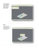
Page 40: ...tify where the supports are placed on the part The support structure will be high lighted green Use the trackball to rotate the platform to view structure Estimate Build Time Click on the estimate build time icon to estimate the time it will take to build the part Front View ...

Page 41: ...This view point button is a front two dimensional viewpoint Help Topics ...

Page 42: ...cally display asking for your User Name and Password After typing in the log in information select Remember my login on this computer and then click on Log In The ProJet 5000 User Guide will become available to help in searching the information in question Isometric View ...

Page 43: ...This view point button is an isometric 3 D viewpoint It scales and orients the display to the standard view point from one corner of the build envelope Mirror ...

Page 44: ...ate a mirror image of one or several parts select the parts and click the mirror icon the dialog box will appear Choose an axis around which to mirror the part and a separation distance click Apply Right View ...

Page 45: ...This view point button is a right two dimensional viewpoint Rotate ...

Page 46: ...Select the part to rotate and click on the rotate icon Use the dialog box to rotate the degree amount in Y X Z directions in the maximum of 180 Scale ...

Page 47: ... differently in each axis Select one or several parts and click on the scale icon the dialog box appears Enter a scale value then click the apply Scale values are absolute A value of 100 always returns the object to its original scale 200 is always twice the size of the original Scale inch to mm ...

Page 48: ... by multiplying 25 4 to the part measurement Select the part and click Scale inch to mm icon A dialog box will ask if you want to proceed with the modifications select Yes to proceed with the parts unit changes or select No to discontinue Scale mm to inch ...

Page 49: ... inch by dividing 25 4 into the part measurement Select the part and click Scale to inch icon A dialog box will ask if you want to proceed with the modifications select Yes to proceed with the parts unit changes or select No to discontinue Select all ...

Page 50: ...Select a multiple parts the parts will high light once selected To manipulate parts on the platform select the Bottom View or Top View icon Selected Part Information ...

Page 51: ...Click on the selected part information icon to display the part s information dialog with details about the currently selected part Selected Parts ...

Page 52: ...View selected parts enlarges the selected parts until they fill the viewing area Shaded Display ...

Page 53: ...Using a Shaded Display allows visualization of the solid design structure of a part When using the wireframe display toggle back to the Shaded Display to view the solid design Top View ...

Page 54: ...This view point button is a top two dimensional viewpoint It allows you to move the selected parts on the build envelope Translate ...

Page 55: ... box to move parts by entering inch values The dialog box allows relative movement parts are moved from their current location in specified X and Y axis as well as absolute parts are specified in the specified X Y coordinates Undo ...

Page 56: ...Click the undo icon to bring part back to its previous state after changes have been made Undo Zoom ...

Page 57: ... build envelope will reduce incrementally until they are at the normal viewing area Verify Verification detects and fixes problems in the STL Also individual STL part can be verified by selecting it and then clicking the Verify icon View All Parts ...

Page 58: ...View all parts display the parts and enlarges them as much as possible omitting empty portions of the build envelope View Platform and Parts ...

Page 59: ...This predefined view zooms the view to include the entire build envelope and all the parts on the platform Wire Frame Display ...

Page 60: ...Using a wire frame allows visualization of the underlying design structure of a part Zoom ...

Page 61: ...ag across the area that you wish to zoom in on for part detail 8 2 Save a Build Job Prepare and save build job s on your PC Later submit the job skipping preparation steps A saved job is specific to a single PC and can only be built or deleted from that PC Click a printer s icon in 3 D printer s window to open the Info window ...

Page 62: ...ve Job option enabled reaches Pending status another job with the suffix _s is added to the queue For more information see and Build Jobs in your ProJet Client online Help for more information Saving Repeat Confirming 8 3 Submit a Build Job Make certain the printer is Off Line during the job submittal process Place the printer on line after the job is submitted Click on printer s icon in the print...

Page 63: ...click on several STL files Add parts in Preview window After you have added at least one STL file use Preview window to view build jobs in three dimensions and to add more STL files if desired Sample STL files are in the 3 D Modeling Client Samplesfolder Browse files in Select CAD files window When files are selected file names appear in build job parts list of Submit dialog box Click button on Su...

Page 64: ...ons Parts shrink in X and Y The degree of shrinkage depends on part geometry To improve part accuracy apply the X Y and Z Shrink Comp values below initially then measure your parts and refine these values DIM SHRINK COMP INIT x 1 12 y 1 19 z 0 00 Click on Submit dialog box Preview Manipulate parts interactively in the Preview window s virtual printer 3 D build workspace ...

Page 65: ...view is different than applying Shrink Comp values in the Default Job Options dialog box Applying scale percentages changes nominal part dimensions in the STL file s Applying Shrink Comp percentages does not change nominal part dimensions in the STL file s Rather Shrink Comp adjusts for expected shrinkage during the build so the actual final part dimensions more closely match the nominal dimension...

Page 66: ...lean and free of debris If required press and PLATFORM EMPTY Y N NO remove build platform from the printer to replace See 7 2 Install Remove Material Bottles and Build Platform Close chamber door and press When the Operator panel LCD shows press If the display ONLINE PLATFORM EMPTY Y N YES shows please Empty Waste Drawer waste on the next build will exceed waste capacity open the waste drawer and ...

Page 67: ...Jobs The client software will not send build jobs to the printer until job confirmed by selecting checkbox on Submit dialog box or Preparation Only resubmit a saved build job Click printer s icon in client software to open printer s Info window Select build job with of or Job Status Needs Confirm Saved Click button or choose located on the tool bar of the printer s window Confirm Job Confirm ...

Page 68: ...nerates a Pending build job whose name lacks the _s suffix However saved jobs remain in the queue 8 4 1 Delete Build Jobs 8 4 2 Pause Build Job 8 4 3 Abort Build Job 8 4 4 Repeat Build Job 8 4 1 Delete Build Jobs Follow the instructions below to delete one or more jobs from the queue after you submitted Click on modeler s icon in modelers window to open Info window ...

Page 69: ...lick or button or choose or Delete Delete All Job Delete Delete All To delete all jobs click the button or choose If you use and there are saved jobs the ProJet Delete All Job Delete All Delete All Client will ask you if you want to delete saved jobs as well as other ones ...

Page 70: ...ed in response to the modeler completes current layer or its current task Then moves the platform forward YES PAUSE JOB Y N while chamber door and waste drawer remain locked Press again to resume paused job If you don t press again the paused PAUSE PAUSE job resumes automatically after 5 minutes If you press in response to the job does not pause and the confirmation prompt disappears NO PAUSE JOB ...

Page 71: ...d Moves the platform forward and unlocks the chamber door Displays abort job_name remove print You can now the platform remove See 7 2 Install Remove Material Bottles and Build Platform If you press in response to the job does not abort and the confirmation prompt disappears NO ABORT JOB Y N 8 4 4 Repeat Build Job Do not select Repeat from the Operators Panel after a test print Press scroll to hig...

Page 72: ... and disposal of regulated materials Keep disposal records if local law requires Caution Wear protective gloves before removing any waste material Be careful not to spill drop or expose others to these materials Dispose the material according to your local regulatory guidelines When removing the draped portion of the bag be careful not to spill the material that may be on the top portion of the ba...

Page 73: ...o leave your printer in either standby or conserve mode instead of shutting down if the printer is to be used within 7 to 10 days of last build After printer is idle more than 2 hours up to 72 hours it enters Standby or Conserve mode respectively In these energy saving states the printer s heaters are partially cooled and many other components are disabled The heaters are cooler in Conserve mode m...

Page 74: ...uide 8 9 Shrink Compensation for VisiJet MX Part Material Material shrinkage occurs in thermoplastics as they transition from liquid state to solid change in density In the case of photopolymers used in the Multi Jet building process this shrinkage can occur during the curing stage of printing The ProJet Accelerator Client Software has features built in to allow a user to compensate for the natura...

Page 75: ...be made using calipers or more advanced metrology methods b Make note of the X and Y dimensions of the printed part and mark them as XPART and YPART c NOTE If the measurement of the finished part is different from the measurements of the CAD model fine tune the accuracy using scaling factors 4 Determine Scaling Factor to use for the next build Use the following formula calculate the scaling percen...

Page 76: ...inter down time 9 1 Cleaning Printer Surfaces 9 2 Cleaning the Waste Drawer 9 3 Preventive Maintenance 9 4 Return Printer for Repair 9 5 UV LED Cleaning Procedure 9 5 1 UVLED Board Removal Procedure 9 6 Cleaning MDM Areas 9 7 Changing the Charcoal Fan Filter 9 8 Printhead Maintenance 9 1 Cleaning Printer Surfaces Do not remove any outer panels when cleaning the printer Panels must only be removed ...

Page 77: ...y actions when buttons are pressed Remove dirt grease and build material residue from operator panel buttons display window by spraying an ammonia based cleaner e g Windex on a clean lint free cloth then gently wiping the buttons and display window 9 2 Cleaning the Waste Drawer Review VisiJet material handling and disposal safety guidelines in section of this guide before cleaning Part Material Sa...

Page 78: ... for Repair Guidelines for repacking the printer When shipping the printer for service or repair use the original shipping carton and packing material Shipping damage as a result of inadequate packing is your responsibility If you have already disposed of the packing material contact 3D Systems for information on Customer Support repacking the printer 9 5 UV LED Cleaning Procedure Each LED has gla...

Page 79: ...artially cured resin on the LED window If liquid uncured resin is on the surface use alcohol and Q tips as in Step 4 When there Is resin or dust on the LED window until hard particles on the window are completely removed If partially cured resin or sticky substance is stuck on the LED window a piece of wood or hard plastic scraping tool or the other side of Q tip can be used to remove by scraping ...

Page 80: ...oard Removal Procedure 9 5 1 UVLED Board Removal Procedure CAUTION To prevent personal injury or damage to the modeler shut down the modeler and disconnect the power before performing the UVLED Board Removal Procedures Wear protective eye wear and gloves Electro static protection for grounding is required when removing the circuit board to avoid damage to the board If you do not feel that this is ...

Page 81: ...DM Areas Verify that the printer is OFFLINE Wear protective gloves Open the side panels and gently scrape off any material adhered to the metal surfaces Use a flexible plastic scraper to avoid damaging the paint DO not clean the backside of the MDM Vacuum inside around the MDM clamps and the back area around manifold to remove the scrapings Wipe the inside surfaces using a clean cloth and all purp...

Page 82: ...er These areas are heated and can be hot Visually inspect the UV LEDS to ensure they do not need replacing or if they are clean If cleaning is required see the UVLED CLEANING PROCEDUR Clean areas where materials debris may have accumulated Inspect the planerizer for damage Also wipe the planerizer roller using a lint free cloth and acetone Clean the printhead s array plate using a lint free cloth ...

Page 83: ...r of support material bottles in the left material delivery system are four 4 Add support material bottles 10 3 Status and Message Lines Messages appear either on the Status line or the Message line Read both lines together to determine the exact state of the modeler The Status line generally indicates current state of the modeler The Message line shows the action to take to complete a function an...

Page 84: ... MENU PAUSE ACKNOWLEDGE The button was pressed The modeler is acknowledging PAUSE and complying with the command None NOTE If you press during a print job the PAUSE current layer or process is completed before the pause takes effect PLEASE WAIT The modeler is cooling to shutdown temperature Wait for the modeler to complete its shutdown procedures Refer to modeler shutdown PRE JOB CHECKS Briefly di...

Page 85: ...hnical Support contacting Technical Support Hotline ensure you have serial number of the printer a brief description of the problem including exact error message displayed on the LCD panel and when the problem occurred while submitting a job during the beginning or end of the build after power off recovery etc 11 1 Communication Errors 11 2 Head Maintenance Station Errors 11 3 Material Feed and Wa...

Page 86: ...modeler requested material The build will abort if it needs to use the questionable bottle to finish the build Install a clean build platform and the build job repeat after the modeler has reached build temperature If error message occurs again contact your Technical Hotline Support Support or build material bottle expired The material identification system detected expired material Follow the dis...

Page 87: ...ION To prevent skin exposure to uncured model material do not handle parts in a build without wearing gloves if a UV lamp problem occurred during the build 11 8 Vacuum Regulator Errors MESSAGE CAUSE ACTION RT_ERROR Printhead Vacuum Low Indicates a fault within the vacuum system Cycle power to the modeler If error message occurs again contact your Hotline Techncial Support RT_ERROR Printhead Vacuum...

Page 88: ...ve Build remove repeat job if desired If the modeler is in Power Off Recovery the build chamber will not be able to open until modeler completes recovery 12 0 Finishing When the build is complete refer to the for information on how to detach parts from build VisiJet Material Handling and Post Processing Guide platform remove support material from parts and clean parts to a smooth finish Basic part...

Page 89: ...3 Projet Quick Reference Guide Click on the link to download a copy of the ProJet 5000 Quick Reference Guide ProJet 5000 Quick Reference Guide 14 4 Facility Requirements Guide Projet 3 D Modelers Facility Requirements Guide 14 5 VisiJet Material Handling and Post Processing Guide VisiJet Material Handling and Post Processing Guide 15 0 Service and Support 15 1 Contacts 15 1 Contacts For informatio...

Page 90: ...gs by helping companies significantly lower production costs and reducing expensive revisions late in the development cycle Enhancing Communication and Collaboration through bringing ideas off flat screens and producing functional 3D prints that can be easily shared critiqued and improved upon Creating Better Designs designers are no longer limited to the number of models they can produce and test...

Page 91: ...geometry authoring tool within the Product Lifecycle Management process and involves both software and sometimes special purpose hardware What is a STL file A stl file is a format used by Stereolithography software to generate information needed to produce 3D prints on Stereolithography machines It is a triangular representation of a 3 D object The surface of the object is broken into a logical se...

Page 92: ...g the build process The chamber door must be closed prior to starting or resuming a build job and is locked when a build is in progress Debug Log is a text file used for obtaining information for resolving potential problems that may occur with the printer Job Scale Percentage Job Scale is used to resize parts during the build process Material Delivery Module stores and feeds the material to the p...

Page 93: ... A Abort Build Job About this Guide Add Cartridge B Build Demo Part Material Part Material Safety Part Material Safety Data Sheet MSDS C Cleaning Surfaces Cleaning the Waste Drawer Communication Errors Contacts Copyright Create STL File s to Build D Delete Build Jobs Disposal E Electrical Empty Waste Drawer Error Messages F Facility Requirements Facility Requirements Guide Familiarization Features...

Page 94: ...ew Build Job ProJet Quick Reference Guide R Regulatory Information Remove Build Platform Remove Part from Build Platform Repeat Build Job Return Printer for Repair S Safety Guidelines Safety Symbols Definitions Save a Build Job Service and Support Shutdown Printer Spilled VisiJet Material Status and Message Lines Submit a Build Job Submit Test Build System Functions System Requirements T Troublesh...

Reviews: