background image


Products


SuperStack II Hub 10 is part of the SuperStack II range of 3Com 


products. Contact your supplier for the latest product information.


Hub 10 hubs


3C16670 SuperStack II Hub 10 12Port TP


3C16671 SuperStack II Hub 10 24Port TP


3C16672 SuperStack II Hub 10 24Port Telco


3C16665 SuperStack II Hub 10 6Port ST Fiber Optic 


Hub 10 management


3C16630A SuperStack II Hub 10 Management Module


3C16632 SuperStack II Hub 10 Advanced RMON Module


Transceiver Modules


Bulletin Boards


Management agent software upgrades are available from these 3Com 


bulletin boards.


Introduction


The Hub 10 24 Port TP is supplied with two mounting brackets and four 


screws. These are used for rack mounting and wall mounting the unit. 


When mounting the unit, you should take note of the guidelines given 


in 


Siting the Hub 10 24 Port TP


 overleaf.


Wall Mounting Hub 10 Units


CAUTION:


 Disconnect all cables from the Hub 10 unit(s) before 


continuing. Remove the self-adhesive pads from underside of 


the unit(s), if already fitted.


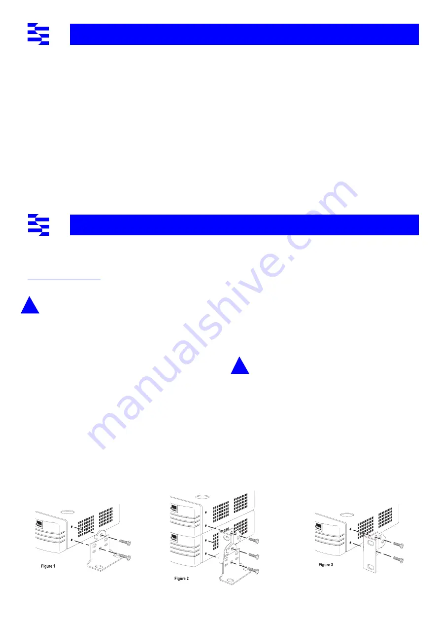
Fitting the brackets to wall mount one unit:


Place the Hub 10 unit the right way up on a hard, flat surface with 


the front facing towards you.


Locate a mounting bracket over the mounting holes on one side 


of the unit, as shown in figure 1 below.


Insert the two screws and fully tighten with a screwdriver.


Repeat the last two steps for the other side of the Hub 10 unit.


Fitting the brackets to wall mount two units:


Stack the Hub 10 units the right way up on a hard, flat surface 


with the front facing towards you.


Locate two mounting brackets over the mounting holes on one 


side of the units, as shown in figure 2 below.


Insert the three screws and fully tighten with a screwdriver.


Repeat the last two steps for the other side of the units.


To wall mount the Hub 10 unit(s):


Ensure that the wall you are going to use is smooth, flat, dry and sturdy. 


Attach a piece of plywood (12" x 20" x 0.5") securely to the wall if 


necessary, and mount the Hub 10 unit(s) as follows:


Position the unit(s) against the wall (or plywood) ensuring that 


the ventilation holes face sideways. Mark on the wall the position 


of the screws holes for both wall brackets. Drill the four holes.


Using suitable fixings and screws (not provided), attach the unit(s) 


securely to the wall (or plywood).


Reconnect all cables.


Rack Mounting Hub 10 Units


The Hub 10 24 Port TP is 1U high and will fit a standard 19inch rack.


CAUTION:


 Disconnect all cables from the Hub 10 unit before 


continuing. Remove the self-adhesive pads from underside of 


unit, if already fitted.


Place the unit the right way up on a hard, flat surface with the 


front facing towards you.


Locate a mounting bracket over the mounting holes on one side 


of the unit, as shown in figure 3 below.


Insert the two screws and fully tighten with a suitable screwdriver.


Repeat the two previous steps for the other side of the unit.


Insert the unit into the 19" rack and secure with suitable screws 


(not provided).


Reconnect all cables. 

P

RODUCTS


AND

 B

ULLETIN

 B

OARDS


3C12060 Female AUI


3C12065 Fiber Optic (ST)


3C12063 TP


3C12066 Coaxial


3C12064 Fan Out (male AUI)


3C12067 FB


3C16060 Bridge MicroModule


Australia


(61) (2) 9955 2073


Japan


(81) (3) 3345 7266


France


(33) (1) 69 86 69 54


Singapore


(65) 534 5693


Germany


(49) (89) 627 32 188


or 627 32 189


Taiwan


(886) (2) 377 5838


Hong Kong


(852) 2537 5608


U.K.


(44) (1442) 438278


Italy


(39) (2) 273 00680 


(fee required)


U.S.


(1) (408) 980 8204

3Com Corporation
P.O. Box 58145
5400 Bayfront Plaza
Santa Clara
CA 95052-8145
USA

c/o 3Com Centre
Boundary Way
Maylands Park South
Hemel Hempstead
Herts HP2 7YU
England

R

ACK

 M

OUNTING

 K

IT

 I

NSTRUCTIONS

Summary of Contents for SUPERSTACK II HUB 10 24-PORT TP

Page 1: ...es must be used to ensure compliancewith these standards Environmental EN 60068 IEC 68 Width 440mm 17 3 ins Depth 224mm 8 8 ins Height 44mm 1 7 ins or 1U Weight 2 7kg 5 9lb Mounting free standing or 19 rack or wall mounted using kit supplied Power Inlet IEC 320 Fuse Protection 2 Amps Power Consumption 28 VA Power Dissipation 96 BTU hr Power Inlet IEC 320 Fuse Protection 2 Amps Power Consumption 36...

Page 2: ...e peut pas être mise en marche des sources de courant IT Impédance à la terre Si vos sources de courant sont de type IT cette unité doit être alimentée par 230V 2P T via un rapport de transformation d isolation de 1 1 avec un point de connexion secondaire étiqueté Neutre branché directement à la Terre à la Masse La Cordon d Alimentation Surmoulé Celui ci doit être approuvé pour le pays auquel il s...

Page 3: ... all TP ports on the unit will be disabled during power up until they are correctly configured and enabled by management software This is only necessary on units which have ports assigned as standby Standby ports in resilient link pairs can only be configured on SuperStack II Hub 10 or LinkBuilder FMS II units Security features are described in the manual which comes with your Hub 10 Management Mo...

Page 4: ... Module port If this LED does not flash there are no packets being received by the unit 8 Collision LED The Collision LED flashes yellow when a packet collision has been detected on a segment connected to one of the 24 twisted pair ports the AUI port or the Transceiver Module port Under normal 802 3 operation collisions occur and cause the Collision LED to flash The probability of collisions incre...

Page 5: ...ect units together Do not use two cables to connect any two units to each other they will not work if you do this Disconnect power from all units that will form part of the new stack Connect the male hub expansion connector of one unit to the female hub expansion connector of the next unit Repeat this process until all the units are connected together Refer to Stacking Units for the number of unit...

Page 6: ...etin Boards The upgrade includes instructions on how to load the agent Managing with an FMS Management Module Managing with a Hub 10 Management Module 3C16630A or a Hub 10 Advanced RMON Module 3C16632 If you have a Hub 10 LinkBuilder FMS or FMS II unit fitted with a Management Module and a LinkBuilder 10BTi in your stack the Hub 10 FMS or FMSII Management Module will manage the stack The LinkBuild...

Page 7: ...driver Repeat the last two steps for the other side of the units To wall mount the Hub 10 unit s Ensure that the wall you are going to use is smooth flat dry and sturdy Attach a piece of plywood 12 x 20 x 0 5 securely to the wall if necessary and mount the Hub 10 unit s as follows Position the unit s against the wall or plywood ensuring that the ventilation holes face sideways Mark on the wall the...

Page 8: ...N S MISUSE NEGLECT IMPROPER INSTALLATION OR TESTING UNAUTHORIZED ATTEMPTS TO REPAIR OR MODIFY OR ANY OTHER CAUSE BEYOND THE RANGE OF THE INTENDED USE OR BY ACCIDENT FIRE LIGHTNING OR OTHER HAZARD Limitation of Liability TO THE FULL EXTENT ALLOWED BY LAW 3COM ALSO EXCLUDES FOR ITSELF AND ITS SUPPLIERS ANY LIABILITY WHETHER BASED IN CONTRACT OR TORT INCLUDING NEGLIGENCE FOR INCIDENTAL CONSEQUENTIAL ...

Reviews: