


Rear Panel Connections
11
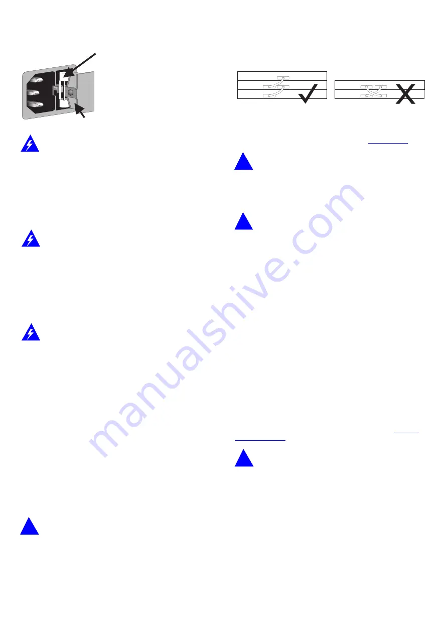
Power Supply and Fuse
WARNING:
Ensure that the power supply is disconnected before
opening the fuse holder cover.
The Hub 10 24 Port TP automatically adjusts to the supply
voltage. The fuse is suitable for both 110V A.C. and 220-240V
A.C. operation.
To change the fuse, release the fuse holder by gently levering a
small screwdriver under the fuse holder catch. Only 2A
anti-surge type fuses of the same type and manufacture as the
original should be used with the Hub10 24 Port TP. Close the
fuse holder.
AVERTISSEMENT:
Assurer que l'alimentation soit débranchée
avant d'ouvrir le couvercle du contenant du fusible.
L'unité s'ajuste automatiquement à la tension d'alimentation.
Le fusible est conventual aux deux opérations 110 V C.A. et
220-240 V C.A.
Pour changer le fusible, dégager le contenant du fusible en
mettant doucement un petit tournevis sous l'arrêt de
contenant du fusible. Seulement les fusibles de types 2A
anti-transitoires du même type et fabricant que l'original
doivent être utilisés.
WARNUNG:
Vor dem Öffnen der Sicherungshalterung das Gerät
vom Netzstrom trennen.
Das Gerät stellt sich automatisch auf die
Versorgungsspannung ein. Die Sicherung ist sowohl für 110V
A.C. wie für 220-240V A.C. geeignet.
Zum Auswechseln der Sicherung durch leichtes Heben mit
einem kleinen Schraubenzieher die Abdeckungsklappe der
Sicherungshalterung lösen. Sicherungen nur durch gleichen
Typ und Wert wie die Originalsicherung ersetzen. Sicherung
auswechseln und die Klappe der Sicherungshalterung wieder
schließen.
12
Socket for Redundant Power System
Only connect a 3Com Redundant Power System, option 3C565047, to
this socket. For details, follow the installation instructions in the guide
accompanying the Redundant Power System.
13
Management Module or Advanced RMON Module Slot
The Hub 10 24 Port TP can be fitted with an optional SuperStack II Hub
10 Management Module or Advanced RMON Module. When the module
has an IP/IPX address, you can then use SNMP management to manage
the stack containing the unit.
CAUTION:
Do not remove the Management Module blanking
plate with the power still connected.
For instructions on installing either module in an Hub 10 unit, refer to
the guide that accompanies the module. You will need to remove the
blanking plate to reveal the slot for the module. If you subsequently
remove the Management or Advanced RMON Module from the Hub 10
unit, you must replace the blanking plate to aid the circulation of
cooling air and prevent the entry of dust and debris.
14
Hub Expansion Connectors
You can connect units together in a stack to form a single logical
repeater. You need one Hub Expansion Cable (3C625) for each additional
unit in the stack. The diagram below shows how you connect units
together. Do not use two cables to connect any two units to each other
- they will not work if you do this.
Disconnect power from all units that will form part of the new
stack.
Connect the male hub expansion connector of one unit to the
female hub expansion connector of the next unit. Repeat this process
until all the units are connected together. Refer to
for
the number of units allowed in a stack.
CAUTION:
If you intend to rack or wall mount the units,
connect the units after they have been mounted.
15
Disable On Boot Switch
This switch is located behind the blanking plate covering the
Management Module slot: see
13
. The unit is shipped with this switch
set to Enable.
CAUTION:
Do not disable ports unless you have a
management module installed in your stack
.
16
Management or Advanced RMON Module Power Cable
Connector
This plug, located behind the blanking plate, provides power to an Hub
10 Management Module or Advanced RMON Module, if fitted and
connected. See the guide accompanying the module for installation
instructions.
17
AUI Port
You can connect the unit to any 802.3 transceiver using an AUI cable
(sometimes known as a transceiver cable or drop cable). Connect one
end of the AUI cable to the AUI port on the rear panel of the unit and
the other end to the AUI port on the transceiver. Engage the slide locks
at both ends of the AUI cable.
Ensure that SQE test is disabled.
18
Transceiver Module Slot
A variety of 3Com plug-in Transceiver Modules or the Bridge
MicroModule can be installed in the Hub 10 24 Port TP (see
). Transceivers provide direct network connections to
different media.
CAUTION:
Do not remove the Transceiver Module blanking
plate with the power still connected.
Ensure that SQE test is disabled.
To install a Transceiver Module, refer to the guide that accompanies it. If
you subsequently remove the Transceiver Module, you must replace the
blanking plate to aid the circulation of cooling air and prevent the entry
of dust and debris.
19
Self-adhesive Pads
The Hub 10 24 Port TP is supplied with 4 self-adhesive rubber pads. If
the unit is to be part of a free standing stack, apply the pads to the
underside of the unit; stick a pad in the marked area at each corner of
the unit. Place the units on top of each other, ensuring that the pads of
the upper unit locate with the recesses of the lower unit.
Do not apply the pads if you intend to rack or wall mount the unit.
Correct fuse location
L’emplacement du fusible correct
Richtige Stellung der Sicherung
Spare fuse location - DO NOT USE
L’emplacement du fusible incorrect - NE PAS UTILISER
Falsche Stellung der Sicherung - NICHT VERWENDEN
Enable
TP ports on front panel are enabled on power up. They may
be subsequently disabled via management software.
Disable
TP ports on front panel are disabled on power up until
management software enables them. This is required for
standby ports in resilient links.


