


Copyright © 2014 Linear LLC
41
INSTALLER PROGRAMMING
ACCOUNT REGISTRATION
The
account
registration
process
is
used
to
enroll
the
Control
Panel
with
remote
service
provider’s
Central
Station.
Typically,
the
account
registration
data
is
created
with
the
service
installation
contract
and
then
stored
in
a
database
managed
by
the
Central
Station.
The
data
includes
items
such
as
the
customer
name,
address,
and
the
Central
Station
telephone
number
and
account
number
assigned
to
the
Control
Panel.
If
you
will
be
installing
the
2GIG
Go!Bridge
IP
Communicator,
additional
registration
information
required.
For
details,
see
the
Installation
Instructions
included
with
the
Go!Bridge
IP
Communicator.
WIRELESS (RF) SENSOR
PROGRAMMING
The
Control
Panel
can
be
programmed
with
up
to
48
RF
sensors
of
different
types.
In
addition
to
the
48
multi
‐
purpose
RF
sensors,
you
can
also
program
eight
(8)
RF
remote
control
key
fobs
and
four
(4)
RF
remote
control
keypads
into
the
system.
RF
sensors
#
01
‐
48
report
as
system
sensors
01
‐
48
.
Programming
questions
for
RF
sensor
programming
include:
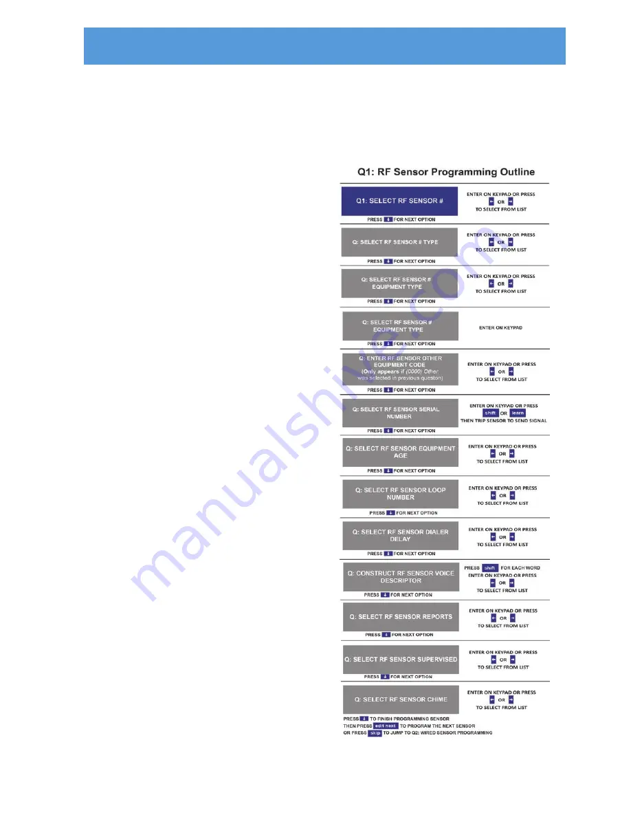
•
Q1:
Select
RF
Sensor
Number
.
Select
sensor
number
01
‐
48.
•
Q:
Select
RF
Sensor
#
Type
.
Select
(01)
Exit/Entry
1
,
(02)
Exit/Entry
2
,
(03)
Perimeter
,
and
so
on.
For
options,
see
"Sensor
Types
(Zones)"
on
page
36.
•
Q:
Select
RF
Sensor
#
Equipment
Type
.
Some
sensor
types
ask
for
the
equipment
type,
others
do
not.
See
"Q:
Select
RF
Sensor
#
Equipment
Type"
on
page
43.
•
Q:
Select
RF
Sensor
#
Equipment
Code
.
Select
the
four
(4)
‐
digit
equipment
code
for
the
sensor
model.
See
"Equipment
Codes"
on
page
40.
•
Q:
Select
RF
Sensor
#
Other
Equipment
Code
.
If
you
select
(0000)
Other
in
the
previous
question,
you
must
enter
this
code.
•
Q:
Enter
RF
Sensor
#
Serial
#
.
Enter
the
serial
number
(typically
a
label
on
the
sensor
or
its
packaging)
or
press
Shift
then
Learn
on
the
panel.
Then
trip
the
sensor
to
transmit
the
serial
number
to
the
panel.
•
Q:
Select
RF
Sensor
#
Equipment
Age
.
Specify
whether
the
sensor
is
(0)
New
or
(1)
Existing
.
•
Q:
Select
RF
Sensor
#
Loop
Number
.
Specify
the
appropriate
loop
number(s)
for
the
sensor.
See
"Q:
Select
RF
Sensor
#
Loop
Number
(1
to
3)"
on
page
44.
•
Q:
Select
RF
Sensor
#
Dialer
Delay
.
Delayed
or
instant
digital
communicator
reports
for
the
sensor.
The
delay
time
is
set
using
the
Dialer
Abort
screen.
•
Q:
Construct
RF
Sensor
#
Voice
Descriptor
.
Name
assigned
to
the
sensor
and
announced
if
programmed.
•
Q:
Select
RF
Sensor
#
Reports
.
Specify
(0)
Disabled
or
(1)
Enabled
whether
RF
sensors
trigger
a
report
to
the
Central
Station
or
not.
•
Q:
Select
RF
Sensor
#
Supervised
.
Control
Panel
checks
for
status
reports
from
the
sensor,
or
does
not
check
for
status
reports]
•
Q:
RF
Sensor
#
Chime
.
Select
voice
announcement
and
chime
options
for
the
sensor.
Q1: RF Sensor Programming Outline
Figure 50
RF Sensor Programming Outline


