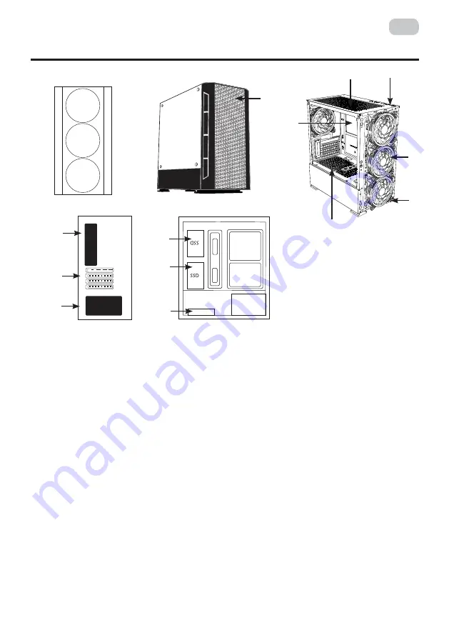
background image

3

UA

ОПИС

1. 

Передня панель:  

1(а) металева сітка;  
1 (b) місце для вентиляторів.

2. 

Задня панель: 


2(a) місце для блока живлення; 
2(b) місце для вентилятора; 
2(c) cлоти розширення для відеокарти, мережевої карти, модема, звукової карти та інше. 

3. 

Основна частина:

 місце для розміщення материнської плати. 

4. 

Внутрішні відсіки:


4(a) 2.5’’; 
4(b) 3.5’’. 

5. 

Верхня панель:


5(а) 1хUSB2.0, 2хUSB 3.0, HD Audio+MIC / Power, Reset, Power LED, HDD LED; 
5(b) пиловий фільтр. 

6. 

Бічна панель (ліва): 

загартоване скло.

* Зовнішній вигляд та комплектація виробу може бути доповнені чи змінені, з метою його  
   вдосконалення чи поліпшення якості товару.

Передня панель

3

6

5 (a)

5 (b)

Основна частина

Бічна панель 
(ліва)

4 (b)

1 (b)

2 (b)

2 (c)

2 (a)

4 (a)

4 (a)

4 (a)
4 (b)

1 (а)

Summary of Contents for GAMING CALLEO WHITE

Page 1: ...RU UA EN COMPUTER CASE OPERATION GUIDE 2E GAMING CALLEO WHITE GB700W...

Page 2: ...cro ATX Micro ATX Mini ITX 5 25 2 5 2 3 3 5 2 1 4 3 120 2 140 1x 120 2 120 240 120 3 120 ARGB 6pin 1 120 ARGB 6pin 1 USB2 0 2 USB 3 0 HD Audio MIC Power Reset Power LED HDD LED VGA 320 CPU 150 200x393...

Page 3: ...3 UA 1 1 1 b 2 2 a 2 b 2 c c 3 4 4 a 2 5 4 b 3 5 5 5 1 USB2 0 2 USB 3 0 HD Audio MIC Power Reset Power LED HDD LED 5 b 6 3 6 5 a 5 b 4 b 1 b 2 b 2 c 2 a 4 a 4 a 4 a 4 b 1...

Page 4: ...the installmen strongly recommended that you refer to your motherboard s instru nstalling stand offs to the case Power Supply Installation Securely install the power supply at the top of the case and...

Page 5: ...tion and tighten it with screws 1 3 5 HDD Installation Install the HDD on the indicated position and tighten it with screws 2 5 SSD Installation Install the SSD on the indicated positions and tighten...

Page 6: ...HDD Installation Install the HDD on the indicated position and tighten it with screws 2 5 SSD Installation Install the SSD on the indicated positions and tighten them with screws Fans Installation Fr...

Page 7: ...7 UA A B C D E F G H Power Button Reset Button Power LED HDD LED USB 3 0 USB 2 0 Headphone Jack Microphone Jack...

Page 8: ...8 RU ARGB LED...

Page 9: ...9 UA RPM dBA CFM V W 1200 10 26 55 12 0 26 0 48 3 12 5 76 6pin 120 x 120 x 25 450 1 2 3 1 FAN1 FAN10 2 MOLEX 3 ON 4 LED...

Page 10: ...10 UA 1 2 3 4 5 6 1 2 3 4 3 CR2025...

Page 11: ...ATX Micro ATX Mini ITX 5 25 2 5 2 3 3 5 2 1 4 3 120 2 140 1x 120 2 120 240 120 3 120 ARGB 6pin 1 120 ARGB 6pin 1 USB2 0 2 USB 3 0 HD Audio MIC Power Reset Power LED HDD LED VGA 320 CPU 150 x x 200x393...

Page 12: ...12 RU 1 1 1 b 2 2 a 2 b 2 c c 3 4 4 a 2 5 4 b 3 5 5 5 2xUSB 2 0 1xUSB 3 0 HD Audio MIC Power Reset Power LED HDD LED 5 b 6 7 3 6 5 a 5 b 4 b 1 b 2 b 2 c 2 a 4 a 4 a 4 a 4 b 1...

Page 13: ...y motherboard has different speci cations for the installmen strongly recommended that you refer to your motherboard s instr nstalling stand offs to the case Power Supply Installation Securely install...

Page 14: ...tion and tighten it with screws 1 3 5 HDD Installation Install the HDD on the indicated position and tighten it with screws 2 5 SSD Installation Install the SSD on the indicated positions and tighten...

Page 15: ...HDD Installation Install the HDD on the indicated position and tighten it with screws 2 5 SSD Installation Install the SSD on the indicated positions and tighten them with screws Fans Installation Fr...

Page 16: ...16 RU A B C D E F G H Power Button Reset Button Power LED HDD LED USB 3 0 USB 2 0 Headphone Jack Microphone Jack...

Page 17: ...17 RU ARGB LED...

Page 18: ...18 RU RPM dBA CFM V W 1 2 3 1 FAN1 FAN10 2 MOLEX 3 ON 4 LED 1200 10 26 55 12 0 26 0 48 3 12 5 76 6pin 120 x 120 x 25 450...

Page 19: ...19 RU 1 2 3 4 5 6 1 2 3 4 3 2025...

Page 20: ...panel 2 120 Radiators mm Front panel 240 Side panel non Rear panel 120 Top panel non Included fans mm Front panel 3 120 ARGB 6pin Side panel non Rear panel 1 120 ARGB 6pin Top panel non HUB for fan co...

Page 21: ...art place for motherboard 4 Internal 4 a 2 5 4 b 3 5 5 Top panel 5 1 USB2 0 2 USB 3 0 HD Audio MIC Power Reset Power LED HDD LED 5 b dust filter 6 Side panel left tempered glass Appearance and equipme...

Page 22: ...anel tempered glass Fastened with screws 4 pcs To disassemble the panel it is necessary to unscrew the screws and carefully remove the panel 2 Side right panel metal It is fixed with screws 2 pcs from...

Page 23: ...tighten them with screws SSD Installation 1 SSD Installation 2 3 5 HDD Installation Install the HDD on the indicated position and tighten it with screws 2 5 SSD Installation Install the SSD on the in...

Page 24: ...troller Fan Installation on rear panel 1 Rear fan installation 2 1x120mm ARGB fan is installed in the case on the rear panel 3 Fan connection 6 pin to the controller the installment of stand offs it i...

Page 25: ...25 EN ARGB FAN CONNECTION DIAGRAM INSTRUCTION ARGB fan connection diagram Power supply LED light bar...

Page 26: ...l 2 Ice Green Ice Blue Green M M AUTO voice control model 3 Pink Purple Blue Brightness Brightness OFF 1 Connect the fans to the controller in the designated connectors FAN1 FAN10 2 Connect the contro...

Page 27: ...nstalled in cases please check how securely they are fixed or remove it before preparation of case for transportation 3 Avoid contact with moisture or water on the surface or inside of case to prevent...

Page 28: ...2 1 2 3 4 5 6 12 __________________________________________________________________ 18 04073 0 800 300 345 044 230 34 84 390 55 12 www erc ua service...

Page 29: ...2 1 2 3 4 5 6 12 _____________________________________________________________...

Page 30: ...applicable law 4 The product is withdrawn from the warranty in case of violation by the consumer of the operating rules set forth in the instruction manual 5 The product is removed from warranty servi...

Page 31: ...eller stamp Date of application Date of completion Cause of damage Coupon 3 Seller stamp Date of application Date of completion Cause of damage Product information Product Model Serial number Seller I...

Reviews: