


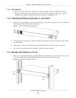

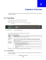


Chapter 2 Hardware Overview
MGS3750-28F User’s Guide
13
2.1.3 Power Connector
Make sure you are using the correct power source as shown on the panel and that no objects
obstruct the airflow of the fans.
Use the following procedures to connect the Switch to a power source after you have installed it.
Note: Check the power supply requirements on the panel, and make sure you are using
an appropriate power source.
Keep the power supply switch and the Switch’s power switch in the OFF
position until you come to the procedure for turning on the power.
Use only power wires of the required diameter for connecting the Switch to a power supply.
2.1.3.1 AC Power Connection
Connect the female end of the power cord to the power socket of your Switch. Connect the other
end of the cord to a power outlet.
2.1.3.2 DC Power Connection
The Switch uses a single ETB series terminal block plug with four pins which allows you to connect
up to two separate power supplies. If one power supply fails the system can operate on the
remaining power supply. Use two wires to connect to a single terminal pair, one wire for the positive
terminal and one wire for the negative terminal.
Note: The current rating of the power wires must be greater than 20 Amps. The power
supply to which the Switch connects must have a built-in circuit breaker or switch
to toggle the power.
Note: When installing the power wire, push it firmly into the terminal as deep as possible
and make sure that no exposed (bare) wire can be seen or touched.
Exposed power wire is dangerous. Use extreme care when connecting a
DC power source to the device.
To connect a power supply:
1
Use a screwdriver to loosen the terminal block captive screws.
2
Connect one end of a power wire to the Switch’s
RTN
(return) pin and tighten the captive screw.
3
Connect the other end of the power wire to the positive terminal on the power supply.
4
Connect one end of a power wire to the Switch’s
-48V
(input) pin and tighten the captive screw.
5
Connect the other end of the power wire to the negative terminal on the power supply.
6
Insert the terminal block plug in the Switch’s terminal block header.


