Chapter 2 Hardware Overview
MGS3750-28F User’s Guide
11
• VT100
• Terminal emulation
• 115200 bps
• No parity, 8 data bits, 1 stop bit
• No flow control
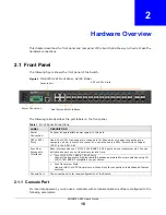
Connect the male 9-pin end of the console cable to the console port of the Switch. Connect the
female end to a serial port (COM1, COM2 or other COM port) of your computer.
2.1.1.1 Default Ethernet Negotiation Settings
The factory default negotiation settings for the Gigabit ports on the Switch are:
• Speed: Auto
• Duplex: Auto
• Flow control: Off
• Link Aggregation: Disabled
2.1.1.2 Auto-crossover
All ports are auto-crossover, that is auto-MDIX ports (Media Dependent Interface Crossover), so
you may use either a straight-through Ethernet cable or crossover Ethernet cable for all Gigabit port
connections. Auto-crossover ports automatically sense whether they need to function as crossover
or straight ports, so crossover cables can connect both computers and switches/hubs.
2.1.2 Transceiver Slots
These are slots for mini-GBIC (Gigabit Interface Converter) transceivers or 100 Mbps Small Form-
factor Pluggable (SFP) transceivers. A transceiver is a single unit that houses a transmitter and a
receiver. The Switch does not come with transceivers. You must use transceivers that comply with
the SFP Transceiver MultiSource Agreement (MSA). See the SFF committee’s INF-8074i
specification Rev 1.0 for details.
You can change transceivers while the Switch is operating. You can use different transceivers to
connect to Ethernet switches with different types of fiber-optic or even copper cable connectors.
To avoid possible eye injury, do not look into an operating fiber-optic
module’s connectors.
• Type: SFP connection interface
• Connection speed: 1 Gigabit per second (Gbps) or 1 Megabit per second (Mbps)
2.1.2.1 Transceiver Installation
Use the following steps to install a mini-GBIC transceiver (SFP module).
1
Insert the transceiver into the slot with the exposed section of PCB board facing down.
2
Press the transceiver firmly until it clicks into place.

