


GS1200 Series User’s Guide
14
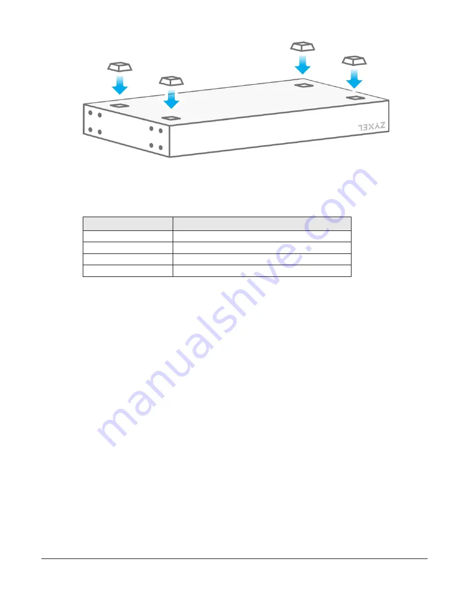
Figure 3
Attach Rubber Feet
2.2.2 Wall Mounting
The distance between mounting holes for each Switch is as follows.
Do the following to mount your Switch on a wall.
1
Drill two holes a distance ‘D’ apart into a wall – see
2
Place two screw anchors in the holes. Screw two screws into the screw anchors. Do not screw the screws
all the way in to the wall; leave a small gap between the head of the screw and the wall.
3
The gap must be big enough for the screw heads to slide into the screw slots and the power cord to run
down the back of the Switch.
Note: Make sure the screws are securely fixed to the wall and strong enough to hold the
weight of the Switch with the connection cables.
4
Use the mounting holes on the Switch to hang the Switch on the screws.
Wall mount the Switch with the Ethernet ports facing down and the
ventilation holes on the side.
Table 2 Wall Mounting Distances
MODEL
DISTANCE ‘D’ BETWEEN MOUNTING HOLES
GS1200-5
91 mm / 3.58 in
GS1200-8
75mm / 2.95 in
GS1200-5HP V2
65mm / 2.55 in
GS1200-8HP v2
180 mm / 7.09 in
Содержание GS1200 SERIES
Страница 8: ...8 PART I User s Guide ...
Страница 26: ...Chapter 5 Initial Setup Example GS1200 Series User s Guide 26 ...
Страница 39: ...39 PART II Technical Reference ...