25 / 61
Identification: MD-AL-GI-00
Rev. 4.0 of 31.01.18 - Application: GID
Manual of 07/06/2019 Rev. 2.1 “User Manual for 1.1K-3K TL”
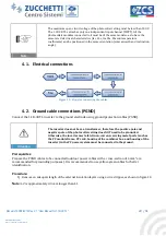
Figure 17 – Positive (1) and Negative (2) MC4 connectors
Note
The positive and negative metal terminals are packed together with the positive and negative connectors
respectively. Separate the positive and negative metal terminals after unpacking the inverter so as to avoid
confusing the polarities.
Procedure
1)
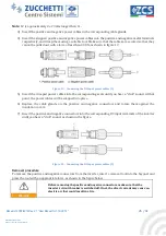
Remove the cable glands from the positive and negative connectors.
2)
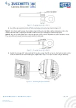
Remove an appropriate length of the insulation layer from the positive and negative power cables by
using a wire stripper, as shown in the figure.
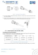
Figure 18 - Connecting the DC input power cables (1)


