20 / 61
Identification: MD-AL-GI-00
Rev. 4.0 of 31.01.18 - Application: GID
Manual of 07/06/2019 Rev. 2.1 “User Manual for 1.1K-3K TL”
Figure 11 – Removing the inverter from its packaging
2)
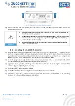
Lift the inverter from its packing box and move it to the installation position, then remove the
polystyrene protections.
To prevent damage and personal injury, hold the inverter firmly when moving, as
it is a heavy piece of equipment.
Do not position the inverter with the input/output terminals in contact with other
surfaces, as these are not designed to support the weight of the inverter. Always
position the inverter horizontally.
When placing the inverter on the floor, make sure to place a support under the
unit to protect its front door.
Attention
3.6.
Installing the 1.1K-3K TL inverter
1)
Correctly position the mounting bracket on the wall, using a level to ensure that it is straight; mark the
five holes using a suitable marker pen. Keeping the hammer drill perpendicular to the wall and avoiding
any sudden movements when drilling, drill the five holes at the points marked on the wall using a 6 mm
drill bit.
In case of errors during drilling, it is necessary to reposition the holes.
2)
Insert the plugs horizontally into the holes made, paying attention to the force and depth with which
they are inserted (make sure the plug completely enters the hole).
3)
Align the mounting bracket with the position of the holes and fix it to the wall using the screws and flat
washers supplied, tightening them properly.
4)
Place the inverter on the mounting bracket
5)
Secure the inverter to the mounting bracket with the M5 bolt to ensure stability.
6)
(OPTIONAL) Depending on the customer’s requirements, the inverter can be locked to the mounting
bracket with a safety lock (not supplied with the kit).


