16
In case the actuator is not stable, it should be immediately stopped. The best way of doing it is changing over the block
of local control BMO “Local” / “0” / “Remote” to the position “0”. If the actuator is not fitted with BMO the motor can be
stopped by pressing the red push-button O/I on the thermal protection. For some types of protection, the motor stops only
for the period when the push-button is depressed. After releasing, it starts running again.
ATTENTION!
Even after this stopping, the actuator circuits are under voltage. Before any further work on the actuator, the supply
voltage must be switched off!!
The change in sequence of phases causing unstable behaviour can also occur during repairs and/or modifications in
the distribution of the three-phase mains supply!
Low-voltage connection
Galvanic interconnection of the circuits of the current position ttransmitter CPT 1A, the circuits of the control signal,
and the circuits of the terminal TEST is realized in the regulator. Connection of these circuits with the electric earth can
only be realized in one of them. The remaining circuits must not be connected to the earth.
In external circuits, galvanic isolation of the active feedback signal from the circuits of the control signal and the signal
TEST must be established. In case this condition cannot be met, it must be brought out as passive signal via the additional
module
(on special order).
The control signal should be lead in by a shielded conductor.
Shielding of the cable of the control signal must be earthed out of the actuator – on the side of the superior system.
On the actuator side, on contrary, its earthing must be prevented.
Setting of regulator ZP2RE4
Adjustable parameters
After fitting to the valve and mechanical adjust-
ment, the correct function of the actuator is provided
for by setting the regulator parameters and starting the
auto-calibration. The regulator parameters can be set
by the push-buttons and/or by the computer.
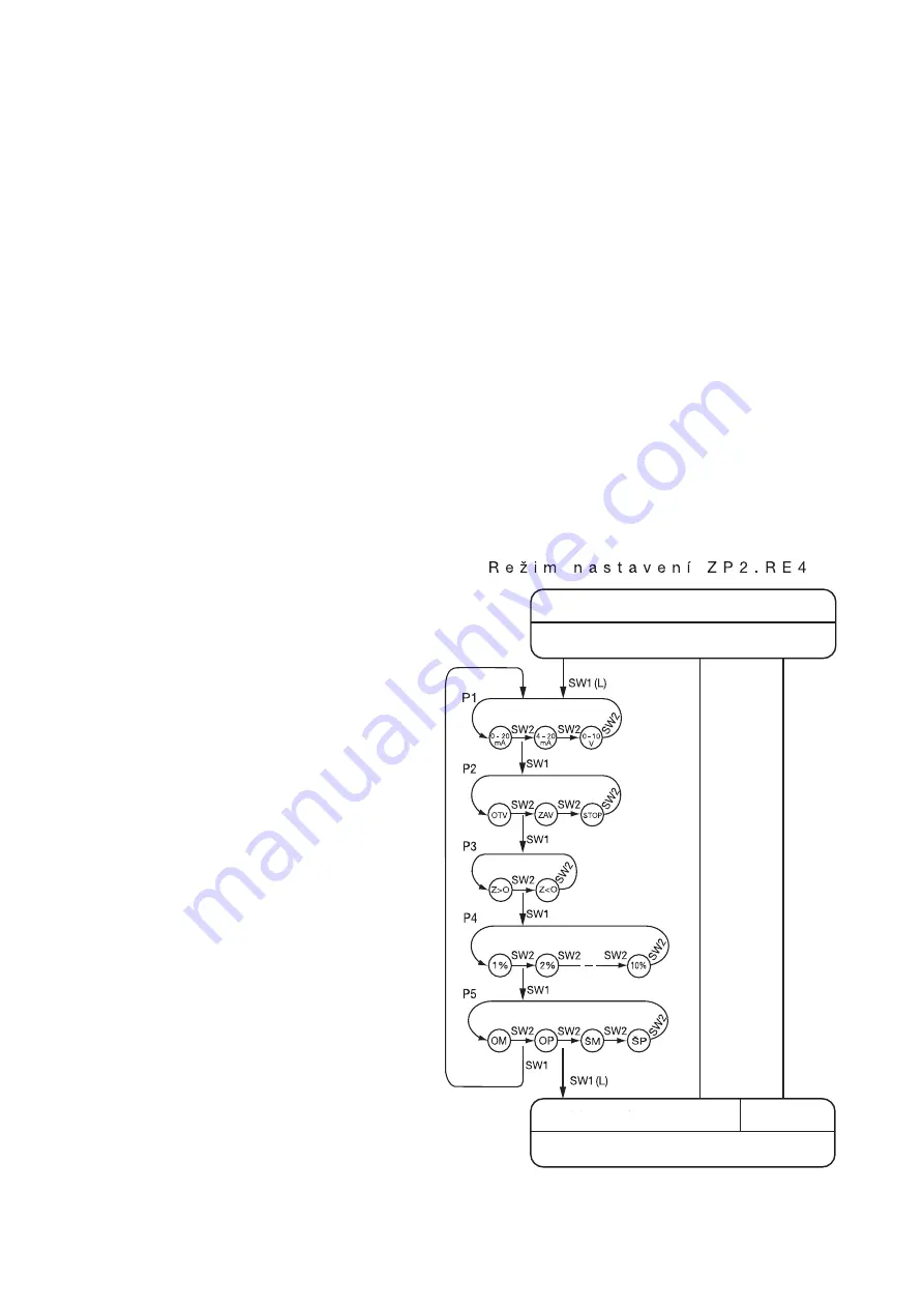
The push-buttons can be used for setting:
Control signal
(P1)
Response to the signal TEST and lost control
signal
(P2)
Mirroring
(P3)
Insensitivity of regulator
(P4)
Type of regulation
(P5)
In addition, the computer can be used for setting:
Active level of signal TEST
Active level of signal TP
In the push-button setting, the changed parame-
ters are stored in the regulator memory in the regime
Auto-calibration. In setting by the computer, the
parameters can also be stored without auto-calibra-
tion.
The auto-calibration is an automatic process during
which the regulator detects additional necessary data:
Check of the position transmitter and the sense of
rotation of the output shaft.
Shifting of the shaft to the limit positions Opened
and Closed and recording of particular value from the
position transmitter.
Measurement of the shaft inertia for both directions
of rotation.
In case of an error-free run, it will store the set
parameters and found-out data in the memory. The
auto-calibration is the most precise when the piping
with the valve is filled with the working medium. Before
starting the auto-calibration, the limit switches
Fig. 2 -
Regime of setting ZP2.RE4
R e g u l a t i o n r e g i m e
In case of an error
, the auto-calibr
ation regime is abandoned
(T
ype of error signaliz
ed b
y
D4)
A
utomatic tr
ansition after error-free r
u
n
Scanning of parameters
Storage
in memory
Auto-calibration regime
Содержание Modact MOKP 100 Ex Series
Страница 2: ......


