background image

12

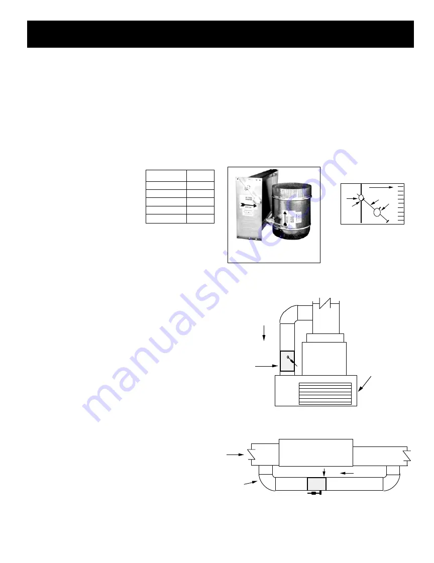
The barometric bypass damper is for systems 5 tons or under. It utilizes
a weighted damper blade to maintain constant duct pressure. This
allows for easy installation without the need for electrical power or
wiring. The round barometric damper can be installed in any position. It
is an efficient solution for small system fan capacity control.

SIZING: 

When only the smallest zone is calling, the maximum

amount of excess supply air will flow through the bypass damper. To
determine the proper size bypass damper to use, do the following steps:

Step 1: Calculate bypass air volume as follows.
A) Calculate total air volume at 400 CFM 

per ton.

B) Calculate air volume of smallest zone in

CFM.

C) Calculate bypass air volume by subtract-

ing the smallest zone air volume from
the total.

(A - B = C)

Step 2:  Select damper from sizing table.
Once you have calculated the bypass air volume from Step 1, use the
BAROMETRIC BYPASS SELECTION TABLE. From the table, select the
bypass damper with the CFM rating equal to or greater than the value

calculated in Step 1. For rectangular barometric dampers, use a
ductulator to convert from round to rectangular.  

If bypassing more than 2000 CFM, use electronic bypass damper.

Example:

You have a 4 ton system. Your smallest zone will use 500

CFM.  The total CFM is 1600 CFM (400 * 4).  Your bypass CFM is 1100
(1600 - 500). From the table, you determine that a 12” bypass damper
is needed.

Do not use the barometric bypass in any system over 5 tons.
For systems over 5 tons, or to bypass more than 2000 CFM, use the
electronic bypass.

RECTANGULAR & ROUND

BAROMETRIC BYPASS

BYPASS DAMPERS – BAROMETRIC

AIRFLOW

1

2

4

3

1. Damper Shaft
2. Lock Nut
3. Lever Arm
4. Counter Weight

BAROMETRIC BYPASS

DAMPER

Diameter

CFM

9”

650

10”

800

12”

1200

14”

1600

16”

2000

BAROMETRIC BYPASS

SELECTION TABLE

INSTALLATION

The round barometric bypass damper can be installed in any position.
This damper is factory set for horizontal installation and can be field
modified for vertical installation.  Do not run speed screws into damper
housing. Screws may interfere with damper travel. Make sure counter
weight is not obstructed in any way.

a)

Install the bypass damper between the supply and return
plenums of the unit. It must be the first tap off the supply plenum.

b)

Be sure the air flows through the damper in the proper direction
as indicated by the arrow on the damper. Airflow is always
from supply to return plenum. Be certain the damper shaft
is horizontal.

c)  Loosen counter weight with Allen wrench.
d)

Loosen lever arm from damper shaft and allow to hang straight
down.

e)

Fully close damper by grabbing damper shaft on side attached
to lever arm and turning clockwise until it stops.

f)

While holding the damper fully closed, rotate the lever arm a
little to the right (facing the damper) and then screw in to
tighten to the damper shaft.  Then tighten lock nut.

g)

Be sure the damper is being held closed by the counter weight.
Proceed to setup

.

AIRFLOW

AIRFLOW

RETURN

BAROMETRIC 

BYPASS

HORIZONTAL APPLICATION

SHEET METAL

PIPE

SUPPLY

PLENUM

A/C UNIT

OR

FURNACE

A/C UNIT

OR

FURNACE

RETURN

AIR 

PLATFORM

BAROMETRIC

BYPASS


RETURN AIR GRILLE

AIRFLOW

SUPPLY

PLENUM

VERTICAL APPLICATION

Содержание DIGI3U

Страница 1: ...DIGI3U Three Zone Universal Controller for Gas Electric or Heat Pump Applications Installation Guide Part D3MAN Zoning Systems That s all we do 3 Zone Controller for the RNC Market October 2011...

Страница 2: ...the controller The resistor is used in place of the LAT for 2 zone Gas Electric installations that do not have a bypass When bypass is used the optional LAT leaving air sensor must be connected in pla...

Страница 3: ...s LAT capacity control is not applied a field supplied freeze protection and high limit device must be installed to protect equipment This should only be applied to designs in which both zones are app...

Страница 4: ...2 W WIRING GAS ELECTRIC DIGI3U S S terminals for LAT capacity control If not applied leave 1k ohm resistor in place and field supplied high and low limits should be added Transformer damper transforme...

Страница 5: ...ition for unit energizing reversing valve for cool place in B position for unit energizing reversing valve in heat JP2 Heat Pump or Gas Electric jumper is used to configure controller Factory set for...

Страница 6: ...12va per damper TR SERIES DAMPER M M 1 2 3 3 TR1 TR2 2 1 DIGI3U SYSTEM CONTROLLER ONE TO THREE TR SERIES DAMPERS Fused 24V 40VA Transformer Transformer and 2 amp fuse TR SERIES DAMPER M M 1 2 3 3 TR1...

Страница 7: ...puts to furnace and dampers After all calls are satisfied controller will initiate a 3 minute purge During this time controller will not allow any calls for heat or cool Cool Operation without LAT If...

Страница 8: ...n place to function in this mode Changeover Gas Electric While controller is operating in heat or cool if another thermostat places a call for the opposite mode a changeover sequence will begin The co...

Страница 9: ...ter all calls for cooling are satisfied Y G and all damper LEDs will go off and controller will initiate a 3 minute purge During this time controller will not allow a call for heat or cool Heat Mode w...

Страница 10: ...energized PWR Power LED orange On when DTHP4A is powered Flashing during capacity control cutout DPR Damper status LED red One per damper On when damper is closed Emergency Heat Operation To put the...

Страница 11: ...control of the unit based upon thermostat input Occasionally software upgrades may become available If so the DIGI3U software can be field upgraded by changing this microcontroller F HVAC System Statu...

Страница 12: ...on supports a synchronous 24V AC 60Hz 12VA motor and termi nal board The motor is designed for continuous full stall operation Special winding and heavy duty gearing provide for long motor life and ea...

Страница 13: ...or to bypass more than 2000 CFM use the electronic bypass RECTANGULAR ROUND BAROMETRIC BYPASS BYPASS DAMPERS BAROMETRIC AIRFLOW 1 2 4 3 1 Damper Shaft 2 Lock Nut 3 Lever Arm 4 Counter Weight BAROMETR...

Страница 14: ...Damper incorrectly wired Correct damper wiring Emergency Heat does not Work STAT 1 must make heat call in Emergency Heat Verify heat call STAT 2 and STAT 3 can make Emergency heat call after STAT 1 V...

Страница 15: ...on and blower fan is running 15 Verify air is being delivered to zone 1 and not to any of the other zones 16 At zone 1 verify air is coming out of the register diffuser 17 At next zone a Verify air is...

Страница 16: ...9963 Fax 714 898 6802 Visit our Web Site http www zonexsystems com PATENTED PRODUCT Zonex Systems reserves the right to discontinue or change at any time specifications or designs without notice and w...

Отзывы: