background image

4

©2017 Guangzhou ZHIYUAN Electronics

Date: 2017/05/22

User Manual

V1.00

Guangzhou ZHIYUAN Electronics Co., Ltd.

CAN-bus recording analyzer

CANREC User Manual

3

Chapter

Chapter

3:

3:

Description

Description

and

and

Function

Function

3.1 About this chapter

This chapter describes connection terminals and ports of the CANREC, including its
communication cable and test suit.

3.2 Connection Terminals (Back panel)

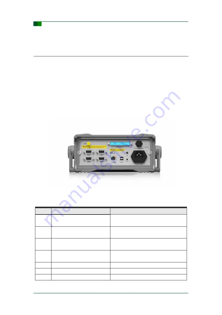
Figure 3- 1 shows connection terminals of CANREC back panel. For the description
of connection terminals, please see Table 3- 1.

Figure 3- 1: Connection terminals

Table 3- 1: Connection terminal description (from left to right)

No.

Description

Remarks

1

WLAN interface

54M 802.11b/g/n wireless WIFI interface, not

support yet.

2

4-channel CAN interface with data

and waveform recording (DB9 port)

Two of them can be specified as the CAN

interface with waveform storage.

3

4-channel CAN interface with data

recording only

Only for CAN message recording

4

Gigabit Ethernet interface

Access to PC for data analysis or networking

analysis

5

USB3.0 interface (device)

Access to PC for data analysis

6

12-36V DC power supply interface

Used for vehicle power or DC power supply

7

100-240V AC power supply interface

Used for AC power supply

Содержание CANREC Series

Страница 1: ...troubleshooting Abstract CANREC CAN bus recording analyzer is developed for accidental faults troubleshooting It is used to record multi channel CAN bus data and waveform for long time Users can find...

Страница 2: ...05 22 User Manual V1 00 Guangzhou ZHIYUAN Electronics Co Ltd CAN bus recording analyzer CANREC User Manual Revision Revision History History Version Rev Date Modifications VOL01 2014 11 28 Created th...

Страница 3: ...ated Limit Value of Power Supply 3 2 7 Electrical Connection 3 2 8 Maintenance and Repair 3 Chapter 3 Description and Function 4 3 1 About this chapter 4 3 2 Connection Terminals Back panel 4 3 3 Port...

Страница 4: ...Open working area 27 5 7 4 Message 27 5 7 5 Quick Search 27 5 7 6 Waveform 28 5 7 7 Eye Diagram 29 5 7 8 FFT Transform 30 5 7 9 Statistics 32 5 7 10 Waveform Index 32 5 7 11 Continuous Storage Mode 32...

Страница 5: ...t the instrument from mechanical impact Put the instrument in a dry room the temperature range should be 0 50 and the maximum humidity should not exceed 85 Protect the instrument from sunlight heat mo...

Страница 6: ...tions described in the Technical Parameters section Make sure the vent of instrument is not blocked during operations Always comply with the explanation in the Transport and Storage of chapter 1 2 3 U...

Страница 7: ...he standard international power cord and socket to ensure that an appropriate voltage is supplied to the instrument otherwise the instrument may be damaged and users may have the risk of electric shoc...

Страница 8: ...ase see Table 3 1 Figure 3 1 Connection terminals Table 3 1 Connection terminal description from left to right No Description Remarks 1 WLAN interface 54M 802 11b g n wireless WIFI interface not suppo...

Страница 9: ...ain display panel Display operations 4 Power indicator The red Power indicator is on after power on If the instrument is powered by the battery the green Power indicator is on 5 HDD operation indicato...

Страница 10: ...ignal connection terminal 8 NC Not used 9 NC Not used 3 5 Optional Interface To be compatible with ISO1898 1 2 3 4 5 standard CANREC series product provide 4 PORT connectors which contain 4 kinds of d...

Страница 11: ...one Supported Supported Hardware differential isolation Supported Supported Supported Number of message received 300 billion 600 billion 1200 billion Terminal resistance switch Supported Supported Sup...

Страница 12: ...llation 4 1 Software Installation 1 Start the setup file Get the setup file and double click the file icon shown in Figure 4 1 to start installation as shown in Figure 4 2 Figure 4 1 CANREC software s...

Страница 13: ...ry is C Program Files zhiyuan CANRec Users can modify the installation directory in the above interface and then the interface shown in Figure 4 4 appears after click the Next button 3 Set the Start m...

Страница 14: ...shown in Figure 4 6 appears after click the Next button 5 Make ready for installation Figure 4 6 CANREC installation wizard ready for installation The software installation information is listed in th...

Страница 15: ...Manual Figure 4 7 CANREC wizard in progress of installation In the Installation completed interface users can double click the CANREC software icon on the desktop to run the software or directly chec...

Страница 16: ...e accidental failures are easy to occur Similar to a black box it records CAN data for analyzing the cause of an error upon its occurrence However due to the limits of storage speed and capacity the c...

Страница 17: ...ery to ensure that the device can continue to run 3 hours when power down Comes with 5 inch screen to clearly display current record status and error CAN interface type high speed CAN fault tolerant C...

Страница 18: ...onnect with PC for online analysis Standard version CANREC Standard 2 channel message and waveform storage 6 channel message storage it can export data to PC for offline analysis Basic version CANREC...

Страница 19: ...ce 2 USB Device interface it is used for U disk upgrade 3 Display screen it is used for software display 4 Physical keys include menu keys arrow keys as well as Set Esc OK keys These keys should be co...

Страница 20: ...system function including device ON status sharing setting battery capacity hard disk capacity IP address and other system information 3 Menu bar it corresponds to the key function of physical menu C...

Страница 21: ...shown in the upper area the latest CAN message data collected by the current channel is shown in the lower area Only latest 10 data frames are showed here Users can view the full message and waveform...

Страница 22: ...the modification for the data within a smaller range is only provided with program a the modification for the data within a larger range is provided with two programs 3 Save Perform the setting after...

Страница 23: ...ing interface Figure 5 10 Channel setting view The channel settings contain 3 settings 1 Channel Enable Enable a waveform channel CH1 and CH2 share the waveform channel 1 CH3 and CH4 share the wavefor...

Страница 24: ...The optional sampling ratios include 100 1 50 1 20 1 and 10 1 3 Trigger mode There are 3 pre defined trigger modes full record frame trigger and error trigger and custom trigger mode The frame ID fram...

Страница 25: ...age amplitudes include 1V 4V 8V 20V and 50V Offset Offset voltage of the waveform i e the voltage deviation of the horizontal starting line of the waveform from the center of the screen The offset ran...

Страница 26: ...hen click the Delete key on the menu a prompt dialog box shown in Figure 5 15 will pop up Figure 5 15 Delete a project Click the OK key to confirm the deletion or the Esc key to cancel the deletion op...

Страница 27: ...n a list Click the Clear key on the menu and then a prompt dialog box shown in Figure 5 18 will pop up Figure 5 18 Clear a project list The confirmation and cancelation for clearing operation is same...

Страница 28: ...he possible reason that a project can not be cleared or deleted is the corresponding project has been opened in the analytic software running on the PC In this case the project is deleted as soon as e...

Страница 29: ...the device and a PC Through the network sharing the CAN message and waveform data collected from the device is transferred to the PC for further analysis User can enable or disable the network sharing...

Страница 30: ...ftware after installation If the interface shown in Figure 5 23 appears it indicates the software is installed and runs successfully Figure 5 23 Main software interface 5 7 2 Basic Software Operation...

Страница 31: ...ollows 1 Click the Open button and the dialog box shown in Figure 5 25 will appear Figure 5 25 Open Working Area dialog box 2 Open the local or network working area according to the actual demand 5 7...

Страница 32: ...gram Users can click a message to display its corresponding waveform and view the detailed waveform information in the waveform view window The steps are as follows 1 Click the View key on the menu ta...

Страница 33: ...ayed in the waveform view 6 Click the button to open the Property page list of the current waveform and then the detailed waveform information is displayed as shown in Figure 5 30 Figure 5 30 Property...

Страница 34: ...e area 1 according to the actual demand and the time interval voltage difference and other detailed information can be displayed in the view area This can help users quickly learn the basic status of...

Страница 35: ...uency on the CAN bus 1 Click the View button on the menu tab and then click the FFT button The FFT view window shown in Figure 5 33 appears Figure 5 33 FFT view 2 Click the button to open the Property...

Страница 36: ...36 appears Through this function users can quickly learn the ratio of error frame and normal frame Figure 5 36 Statistics page list 5 7 10 Waveform Index Click the View button on the menu tab and the...

Страница 37: ...5 38 Continuous storage mode 5 7 12 Trigger Storage Mode Figure 5 39 shows the trigger storage mode In this mode after the operation is started the CANREC saves the waveforms on the CAN bus under the...

Страница 38: ...mum amplitude of each CAN message waveform as shown in Figure 5 40 Figure 5 40 Signal quality analysis Uses some column algorithms to score and sort the waveform signal quality of each ID which enable...

Страница 39: ...e CANREC has large capacity SSD it means that it has more storage space than the CANScope the number of stored waveforms is more than 1000 times that of the CANScope Furthermore it is possible for use...

Страница 40: ...r users can define a special bit field in which the curve is displayed as shown in Figure 5 44 Figure 5 44 Custom protocol analysis 5 8 Typical Application High speed train operation fault detection a...

Страница 41: ...ual automobile and new energy automobile CAN communication fault detection and troubleshooting for ship CAN communication exception analysis for coal mine Elevator operation fault detection and troubl...

Страница 42: ...ANREC characteristics Conventional Characteristics Power Supply 100 240VAC50Hz or 12 36VDC Power Consumption 24W Max Storage Temperature 0 55 Working Environment 0 55 for full accuracy 25 55 for 5 err...

Страница 43: ...including reasonable solicitor s fee from any third party due to any commercial use of this manual by any person or unit is born by users ZHIYUAN Electronics as well as its cooperative company and aff...

Страница 44: ...en Office Room 1203 F 12 Electronics Building No 2072 Shennan Road M Futian District Shenzhen TEL 0755 83640169 83783155 Wuhan Office Room 12128 No 158 Luoyu Road Guangbu Village Hongshan District Wuh...

Отзывы: