background image

26

UC5 IM 1-6  April  2002

Installing the UC5 Hardware

This installation should take 15 minutes excluding the time taken to install the
video board.

NOTE:

1. Check that the Digital Duplicator you are using supports an interface.

2. Many Digital Duplicator models do not have the interface option as
standard. Please ensure that the interface option for your Digital Dupli-
cator has been installed prior to installing the UC5.

3. When installing the UC5 on Model C238 Digital Duplicator, do not
install the rubber paper guides on the paper tray.

1. Remove your UC5 and ancillary cables from the box. Ensure the Digital

Duplicator is turned off.

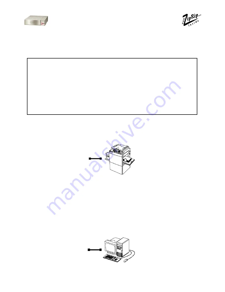
2. Attach  one  end  of  the  long  parallel  cable  supplied  to  the  Digital

Duplicator interface port.  Attach the other end of the same cable
into the port marked “To printer ”.

3. Attach the DB25 end of the Centronics parallel cable to the customer des-

ignated parallel output port on the rear of the computer. Attach the other
end of the Centronics parallel cable to the input port on the rear of the UC5
labelled “To Computer ”.

To Printer

To Computer

Содержание UC5

Страница 1: ...Installation Manual UC5 Revision 1 6...

Страница 2: ...2 UC5 IM 1 6 April 2002...

Страница 3: ...electronic photocopying mechanical copying electrostatic copying recording or other means without express written permission of SMA Pty Ltd Australia Windows is a registered trademark of Microsoft Cor...

Страница 4: ...t Type 600 Parts List 11 Video I F Kit Type 10 Type 15 and Type 85 Parts List 13 Installation Procedures for Interface Kits 14 Model C229 C232 and C233 14 Model C231 and C237 15 Model C238 16 Model C2...

Страница 5: ...uplicators With a UC5 you can print directly from your PC to your Digital Duplicator This will significantly improve the quality of your printed material as well as speed up your printing jobs We are...

Страница 6: ...support Certification CE UL FCC 230V Apparaten skall anslutas till jordat uttag n r den ansluts till ett n tverk 220 240 V 50 60 Hz Raccordez toujours le cordon d alimentation une source de courant c...

Страница 7: ...300 C231 JP1050 5306B 1224B CP306B C237 JP1230 5308L 3150eDNP SD330 C237 JP1250 5308B 1225B CP308B ZipRIP Pro C C229 JP5000 5450 1560 CP450 3350DNP SD400 C239 JP5500 5450 5455 1560 CP450 3360DNP SD450...

Страница 8: ...ckage Contents Components For UC5 Check that you have received the following Items in your UC5 package Cable for connecting to Digital Duplicator Centronics Parallel Cable This User Guide ZipRIP UC5 P...

Страница 9: ...referred to in this manual are described in the diagrams below Power On Indicator Green Activity Indicator Red Powerswitch Power socket Connectusingsupplied cabletoDigitalDuplicator Reset button Conne...

Страница 10: ...you begin the installation you should a Check to make sure that you have all of the items needed to complete a successful installation b Read the documentation to familiarize yourself with the instal...

Страница 11: ...ard 1 3 Insulating sheet 145 200 1 4 Interface Cable Interface Board 1 Set for Part 1A No Description Qty 5 Stud 50mm 2 6 Spacer 10mm 2 7 PCB Stud 64mm 2 8 Harness Support Bracket 1 9 Phillips Pan Hea...

Страница 12: ...19 Phillips Screw with Flat Washer M3 x 25 1 20 Stud Main Board 1 21 Phillips Screw with Flat Washer M4 x 6 1 22 Phillips Screw M4 x 8 2 23 Phillips Screw with Flat Washer M3 x 6 2 Set for 1C No Desc...

Страница 13: ...M4 x 8 2 Video I F Kit Type 10 Type 15 and Type 85 Parts List For Europe Far East and Asia use Type 10 Interface kit For USAand Latin America use Type 15 Interface kit Installation procedure for both...

Страница 14: ...orm step 3 only to connect the controller 1 Remove the rear cover and right side panel of the Digital Duplicator 2 Mount Printed Circuit Board 32 on connector CN102 of the MPU board using two M3x6 scr...

Страница 15: ...it using two screws 35 5 Connect the harness 33 to CN101 of the printed circuit Board and se cure it to the connector bracket using two stepped screws 34 6 Remove the communications port cover plate...

Страница 16: ...crews 2 Remove the I F connector cover C 2 screws 3 Install the I F board D accessories in CN117 E on the MPU 2 screws 4 Attach the cable F accessories to the connector bracket 2 screws and clamp the...

Страница 17: ...the rear cover A 2 Cut away the blindfold cover B on the right rear cover 3 Install the Video I F board C to the MPU 2 screws 4 Connect the cable D to the Video I F board 2 screws 2 spacers NOTE You n...

Страница 18: ...ore mounting Printed Circuit Board Interface 2 attach one end of the Ribbon Cable 12 to the IPU board ribbon cable connector 3 Mount the Printed Circuit Board Interface 2 a Mount a Stud 20 on the Digi...

Страница 19: ...out the communication port cover plate from the lower centre of the rear cover panel b Reinstall the rear and front cover panels 6 Connect the Digital Duplicator and AC power to the Controller a Conne...

Страница 20: ...c Connect one side of the Ribbon Cable 12 to the connector of Mainframe MPU Board d Attach the Printed Circuit Board Interface 2 to the Studs 29 us ing M3x6 Screws 27 e Connect the free end of the Ri...

Страница 21: ...the Studs 5 Attach the Printed Circuit Board Interface 2 to the MPU Control Board taking care to align the left edge with the locking spacers 6 Attach the right side edge of the Printed Circuit Board...

Страница 22: ...icator 14 Mount the Bracket end of the Shielded Cable 4 onto the Studs 24 using two M4x8 screws 26 15 Tie the Shielded Cable 4 to Main Harness using the Tie Band 13 16 Pop out the communication port c...

Страница 23: ...r c Thread the Shielded Cable 4 from the rear chassis to the front chassis under the Digital Duplica tor body d Reinstall the bottom plate e Mount the Bracket of the Shielded Cable 4 on the Studs 8 us...

Страница 24: ...e Connect the Shielded Cable 4 to CN101 of the Printed Circuit Board Interface 2 f Set all switches on DIPSW 101 of the Printed Circuit Board Interface 2 to OFF g Set DIPSW 103 8 of the Mainframe MPU...

Страница 25: ...er Cabling between UC5 and the Computer IBM and Compatibles Parallel 1 Make sure that the customer s computer is turned off 2 Attach the DB25 end of the Centronics parallel cable to the customer desig...

Страница 26: ...ng the UC5 on Model C238 Digital Duplicator do not install the rubber paper guides on the paper tray 1 Remove your UC5 and ancillary cables from the box Ensure the Digital Duplicator is turned off 2 A...

Страница 27: ...nds Turn the Digital Duplicator on next The diagram below illustrates how the UC 5 should be connected Testing your UC5 Once you have set up the UC5 as described above you can produce a test page befo...

Страница 28: ...k like the illustration below NOTE The test page will print as an A4 sheet on a 300dpi Digital Duplicator If the Digital Duplicator has a higher resolution then the output will appear smaller This is...

Страница 29: ...d Indicator Display Meaning On just after the UC5 is turned on UC5 initializing the red light will stay on for 6 seconds Flashing rapidly The UC5 is receiving a print job Continuously on The UC5 has r...

Страница 30: ...o ECP mode Problem Print jobs download to the UC5 but the Digital Dupli cator does not create a master Try the following a Press the Digital Duplicator on line key Some Du plicators do not support Aut...

Страница 31: ...can send a description of the error to the ZipRip web site Please include all details such as PC specification Operating System Application and version being used as well as a detailed account of the...

Отзывы: