UC5 IM 1-6 April 2002
15
Model C231 and C237
Refer to Driver Groups List on page 7
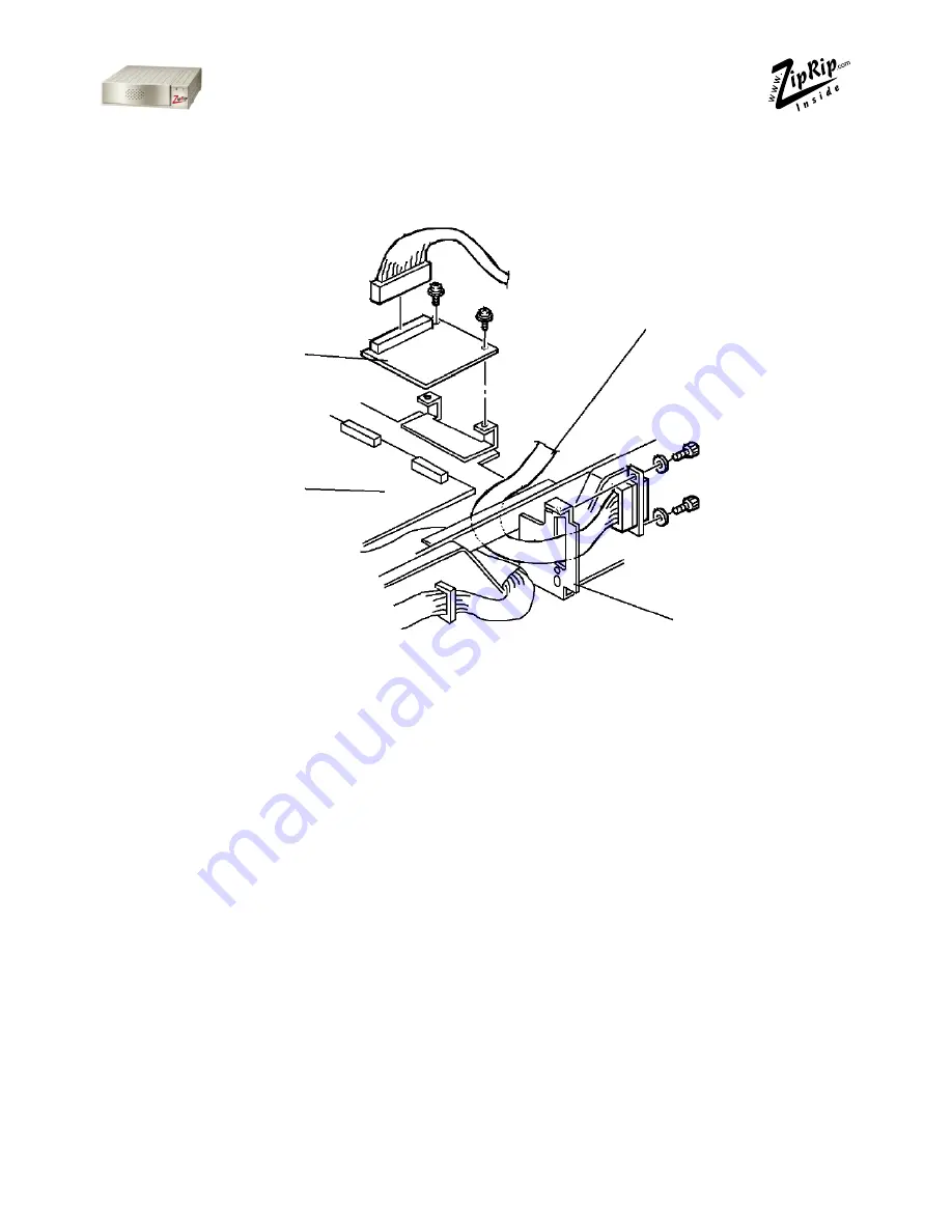
1. Turn off the main switch and unplug the power cord.
2. Remove the upper rear cover.
3. Remove the MPU cover.
4. Connect CN102 of the printed circuit board (32) to CN110 of the MPU
board and secure it using two screws (35).
5. Connect the harness (33) to CN101 of the printed circuit Board, and se-
cure it to the connector bracket using two stepped screws (34).
6. Remove the communications port cover plate (blinding cover) from the
upper rear cover.
7. Reinstall the MPU cover.
8. Reinstall the upper rear cover.
NOTE:
The On-line key on the operation panel is enabled automatically when
the controller and interface kit are installed.
Printed Circuit Board
MPU
Harness
Connector
Bracket
Содержание UC5
Страница 1: ...Installation Manual UC5 Revision 1 6...
Страница 2: ...2 UC5 IM 1 6 April 2002...


