Non-Sound Decoder MX600 - MX638 and Sound Decoder MX640 - MX659 Page 29
#812
- #817
. . .
Group 16
.
. . .
0
. . .
#818
- #823
. . .
Group 17
.
. . .
0
. . .
#508
#509
#510
#511
#512
Dimming values for
“Swiss Mapping”
Special configurations
(0- 31)*8
(only Bits
7…3 are
used)
Bits 0 - 2
0
Each group CV (i.e. #432, 433, 434, 435) can be
linked with one of these five dimming CV’s. The value
to enter is the dimming value (0
– 31) times the func-
tion output number (I.e. dimming value = 16 for func-
tion output 6: 16 x 6 = 96 is the value to enter).
This will dim the relevant function outputs accordingly.
Usable only with function outputs FO0 to FO8.
Bit 0 = 1: suppresses the lighting effect
(SW-Version
36.1 and higher)
Bit 1 = 1: flashing
(SW-Version 37.0 and higher)
Bit 2 = 1: inverted flaashing
(SW-Version 37.0 and
higher)
#399
Speed dependent
headlights
(
Rule 17
)
0 - 255
0
In
conjunction with the “Swiss Mapping” special “high-
beam” setting, see CV #431 = 255; applies to each of
the 13 CV groups (CV #437, 443..):
Switches to high-beam only when the speed exceeds
the value in this CV; based on the decoder internal
255 speed steps.
EXAMPLE:
= 0: High-beam at any speed (incl. stand-still), con-
trolled only by the F-key (i.e. as per CV #430).
=1: High-beam only while driving (not at stand-still),
provided the defined F-key is ON.
= 128: Switches to high-beam when reaching medium
speed.
The application of the “Swiss Mapping” is shown here with the
example
of an SBB Re422 engine.
The function outputs together with the connected
lights or groups of lights are shown here as they exist in
a typical SBB (Swiss) electric locomotive.
The task of the “Swiss Mapping”, with the help of the
function keys
F0 (General ON/OFF), and
F15, F16, F17, F18, F19 and F20,
is to correctly switch the lights in all possible operating
conditions (of course in both directions).
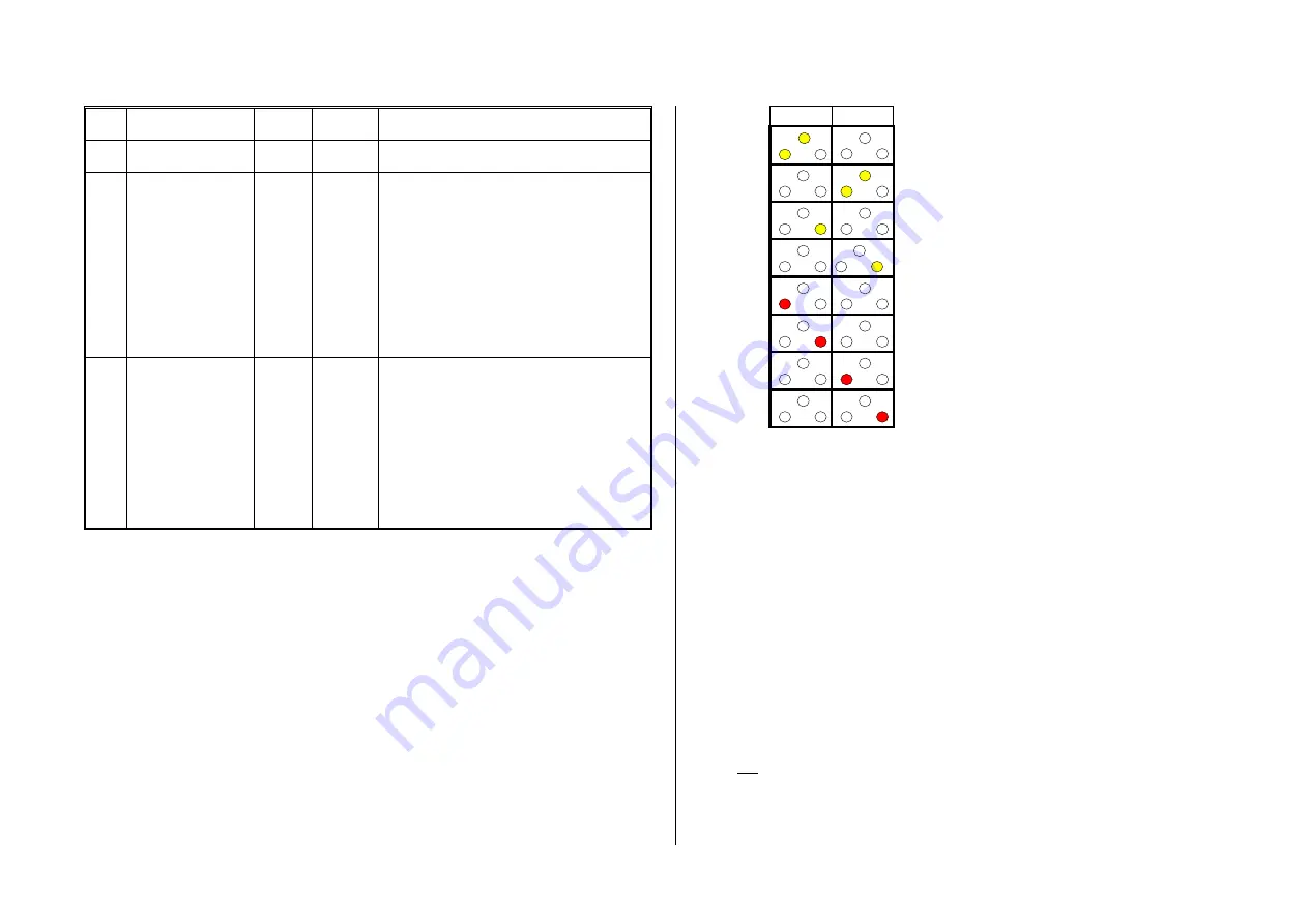
This results in the status table shown on the right,
for which the following configurations are required
in the “Swiss Mapping” (below):
#33 = 133
#34 = 42
#430 = 15
#431 = 157
#432 = 14
#433 = 1
#434 = 15
#435 = 1
#436 = 15
#437 = 157
#438 = 2
.
#439 = 0
#440 = 2
.
#441 = 0
#442 = 16
#443 = 157
#444 = 14
#445 = 1
#446 = 2
.
#447 = 4
#448 = 17
#449 = 157
#450 = 5
#451 = 6
#452 = 15
#453 = 2
#454 = 18
#455 = 157
#456 = 6
#457 = 0
#458 = 4
#459 = 0
#460 = 19
#461 = 157
#462 = 2
#463 = 0
#464 = 1
#465 = 0
#466 = 20
#467 = 157
#468 = 0
#469 = 0
#470 = 0
#471 = 0
Explanation:
The normal NMRA function mapping in CV #33 and CV #34 (front and rear headlight) deter-
mines the lighting in case when F0 is ON and function keys F15
– F20 are OFF:
CV #33 = 133 (= Lfor, FO1, FO6) and CV #34 = 42 (= Lrev, FO2, FO4).
The following CV groups (1. Group: CV #430
– 435, 2. Group: CV #436 – 441 etc.), each group
shown on one line, contain in the first CV the number of the
“F-key” F15, F16, F17, F18, F19,
F20, followed by
the CV’s for the “M-key” and function outputs to be switched.
Note that there are two groups for F15 (CV #430… and #436…) because F15 should switch 3
function outputs simultaneously, but only 2 can be entered per group (A1, A2 for each direc-
tion); one group is suf
ficient for all other “F-Keys”.
All “M-Keys” (the second CV in each group) are all set to “157”; this means that “F0”
and
the
condition of Bit 7 must be met, which means that the selected outputs are only activated if the F
and M keys are ON.
The third to sixth CV’s in each group contain the numbers of the function outputs to be actuated
(where the headlights are coded with “14” and “15”, for all other outputs just use the digit in
FO1, FO2…).
Front
Rear
Lfor
Lrev
FO1
FO2
FO3
FO4
FO5
FO6


