


Handbook
Ucontrol
type-lines PXDM
Date 06/04
TBL02_55-GB06/04
Part.-No. 00153239-GB
Page 90 / 105
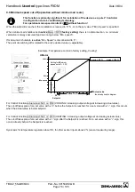
11 14 12
K1
1
= de-energized, terminals 11-14 bridged
0
= energized, terminals 11-12 bridged
21 24 22
K2
1
= energized, bridged 21-24 bridged
0
= de-energized, bridged 21-22 bridged
Max. contact rating
5 A / 250 V AC
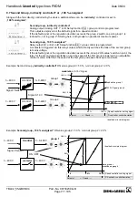
10.4 Function and inverting for relay outputs K1 and K2
Various functions can be allocated to the relay outputs K1 and K2
In case of the same function allocation for K1 and K2, these work parallel.
Function description
--
no Function
Relays remain always de-energized
1 K
Operating indication
(factory setting for K1)
Operation without fault, reports enable ON / OFF
2 K
Fault indication
(factory setting for K2)
At line, motor and controller fault, Sensor fault dependent on
programming, external fault at digital input
3 K
External fault separate
With message at digital input (factory setting if terminals bridged)
4 K
Limit modulation
when over or falling below limits for modulation
5 K
Limit E1
when over or falling below limits for input signal E1
6 K
Limit E2
when over or falling below limits for input signal E2
For modes as controller (higher
2.01
....)
7 K
Setpoint Offset
Deviation between actual value and setpoint to high
8 K
Group control
Switching on fans depending on modulation
for modes as temperature controller with additional functions (
2.03
) ....)
9 K
Heating function
Switch ON point: temperature = Se/- Offset
Switch OFF point: Temperature around hysteresis over switch ON point
10 K
Cooling function
Switch ON point: temperature = Se/- Offset
Switch OFF point: Temperature around hysteresis below switch ON point
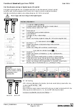
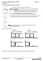
K1 / K2 Inving
The factory preset is the inversion of relay K1 and K2 to „OFF“ (if a function has been programmed).
Switch to „ON“ for inversion (switch-time response depends on the allocated function). Fundamentally, the relays can only
become operative if the electronics’ voltage supply is functioning. At least 2 current phases must be present!
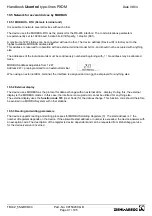
K1 / K2 Inverting
Function Controller status
OFF
ON
1 K
Operation without fault, line suplly okay
1
0
2 K
Fault with indication by relay
0
1
3 K
Ext. Fault at digital input for external fault
1
0
4 K
when over or falling below limits for modulation
1
0
5 K
when over or falling below limits for input signal E1
1
0
6 K
when over or falling below limits for input signal E2
1
0
7 K
setpoint deviation to high
1
0
8 K
Switching on second group
1
0
↓
↑
↓
↑
↓
↑
Содержание Ucontrol PXDM Series
Страница 80: ...Handbook Ucontrol type lines PXDM Date 06 04 TBL02_55 GB06 04 Part No 00153239 GB Page 80 105 ...
Страница 92: ...Handbook Ucontrol type lines PXDM Date 06 04 TBL02_55 GB06 04 Part No 00153239 GB Page 92 105 ...
Страница 96: ...Handbook Ucontrol type lines PXDM Date 06 04 TBL02_55 GB06 04 Part No 00153239 GB Page 96 105 ...
Страница 100: ......


