


Handbook
Ucontrol
type-lines PXDM
Date 06/04
TBL02_55-GB06/04
Part.-No. 00153239-GB
Page 14 / 105
5. Electrical connections (refer also to Enclosure: Connection diagram)
5.1 Mains connection
Power from the mains is connected to terminals: PE, L1, L2, L3, and N. Here, it must be strictly observed that the mains
voltage lies within the allowable tolerance specifications (
F
General description: Technical data and nameplate affixed to
the side).
The neutral conductor connection “N” is only for the leakage current´s reduction. It is of no significance for the function of
the device. The connection is not applicable for power supply networks without a neutral conductor. Since higher leakage
currents may arise by this across the protective-cable connection “PE”, unwanted triggering by mistake may occur in
systems with FI protection circuits.
If the neutral conductor “N“ is not connected and the “PE“ connection is interrupted,
touching can result in dangerously high leakage currents. In this case, EN 50178
Section 5.3.2.1 for devices with leakage current above 3.5 mA must be observed.
5.2 Conditions for the voltage supply
The supply voltage has to correspond to DIN EN 50160 (characteristics of the voltage of public
electricity supply). Unit failures only occur in the same way as the failures of the supply
voltage, which are descriped in the norm.
In countries with a nominal frequency of 60 Hz, the above applies to 60 Hz networks.
Supply voltages that do not comply with DIN EN 50160 have to be checked seperatly.
5.3 Motor connection
The motor leads are connected to the terminals: PE, U, V, W. Several fans can be connected to the controller-the
maximum total current of all motors (maximum rated current for electronic control of the voltage) must not exceed the
current rating for the controller.
If the maximum control current for the electronic voltage control is not known, then allowance for an increase in the motor
nominal current must be made. Typical is this for 2- and 4-pole motors at approx. 25 %, for 6-pole motors at approx. 20
%, for 8- and 10-pole motors at approx. 15 % and higher pole motors at approx. 5 %.
For the control of motors made by other manufacturers (not Ziehl-Abegg), the control characteristics and the maximum
current for electronic regulation of the voltage should be enquired from the manufacturer.
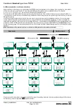
It is recommended that a separate motor protection unit be foreseen for each fan
.
For motors with thermistors :
e.g. type U-EK230E
For motors with thermal contacts :
e.g. type STDT 16 (E) or AWE-SK
(
F
Enclosure: Circuit suggestion for several motors with motor protection unit
type STDT)
5.4 Motor noise
Motor noise can occur when fans are controlled using electronic voltage controllers (Phase
cutting = series “P...”). Such noise can be perceived as a disturbance. This noise is relatively
low for fast-running fans where the noise from the air is high. The noise from motors in slower-
running fans where the noise from the air is less, can be dominated by resonance in the lower
speed ranges.
For systems where noise is critical, we recommend using our Fcontrol series frequency
converters with integrated sinusoidal filter
Содержание Ucontrol PXDM Series
Страница 80: ...Handbook Ucontrol type lines PXDM Date 06 04 TBL02_55 GB06 04 Part No 00153239 GB Page 80 105 ...
Страница 92: ...Handbook Ucontrol type lines PXDM Date 06 04 TBL02_55 GB06 04 Part No 00153239 GB Page 92 105 ...
Страница 96: ...Handbook Ucontrol type lines PXDM Date 06 04 TBL02_55 GB06 04 Part No 00153239 GB Page 96 105 ...
Страница 100: ......


