Controller
24V
D1 D1
1
0
n = 0 -100 %
1
n = 80 %
0
- - - - -
- - - - -
- - - - -
Se
E1
ES
E2
26.05.2010
v_7d_regelung_hand.vsd
3
2
1
1
Setting
“
Setpoint1
”
2
Setting
“
Setpoint2
”
3
Setting
“
Speed manual
”
(depending on device type in: %, Hz, rpm)
EH
Signal for Manual mode extern, E2 Function =
|
2E
|
Se
Sensor
•
“
D1 Inverting
”
=
“
OFF
”
Automatic control at
opened contact / manual operation at closed
contact.
•
“
D1 Inverting
”
=
“
ON
”
: Automatic control at
closed contact / manual operation at opened
contact.
9.10.2.9
Reverse action of control function (
2.01
), Function
|
8D
|
Switchover between: Increasing modulation during increasing actual-value and increasing modulation
during sinking actual-value.
The factory presets for the
“
Control function
”
are dependent on the selected Mode of operation (
Controller Setup - reverse operation of the control function).
When switching over via a digital input, the device works with the opposite function as set there.
Val>Set=n+
Settings in Controller Setup
9.10.2.10
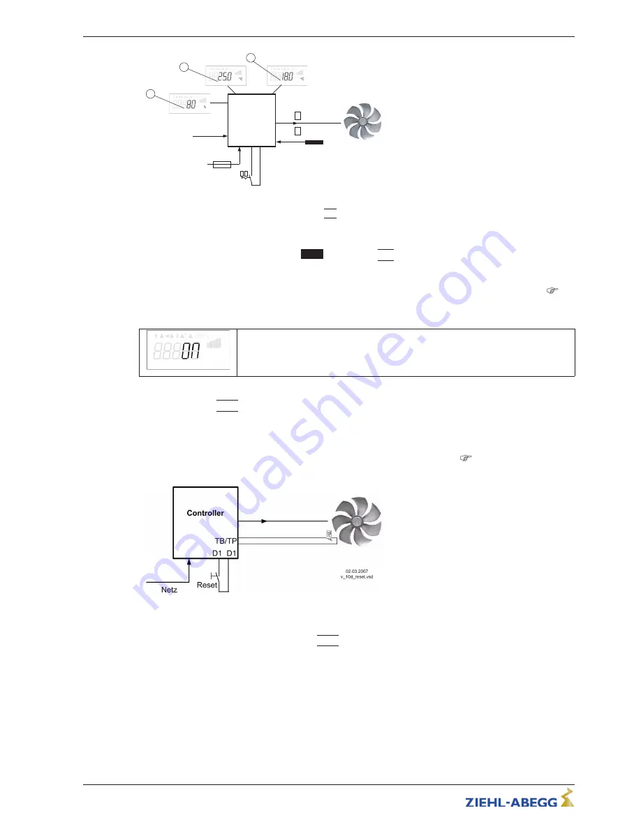
Reset, Function
|
10D
|
Reset via an external push-button in case of a motor fault or a malfunction of the controller.
Example for reset after a motor fault
Reset after motor fault by using an non-locking reset key. The unit switches off when interruption between both
“
TB/TP
”
or
“
TK/PTC
”
terminals, the unit then remains switched off
“
motor fault
”
see (
motor protection). Re-
starting after the drive has cooled down (terminals
“
TB/TP
”
- or
“
TK/PTC
”
bridged) by non-locking reset key
possible.
Contact at digital input e.g.
“
Digital In 1
”
For
“
D1 Inverting
”
=
“
OFF
”
both terminals
“
D1
”
-
“
D1
”
in normal operation interrupted. Reset
after fault by short close.(For
“
Inverting
”
=
“
ON
”
reverse function).
9.10.2.11
Setting Max. Speed ON / OFF function
|
11D
|
The value for
“
Max Speed
”
adjusted in menu
“
Settings
”
, is activated over a digital input. I.e. the unit
works independently of the controller function
fi
rm with this value.
Contact e.g. at ditgital input
“
Digital In 1
”
(depending on device type at terminals
“
D1
”
-
“
D1
”
or
“
D1
”
-
“
24 V
”
).
Operating Instructions
Fcontrol
–
model series FXDM
Programming
L-BAL-E072-GB 1642 Index 008
Part.-No.
65/105


