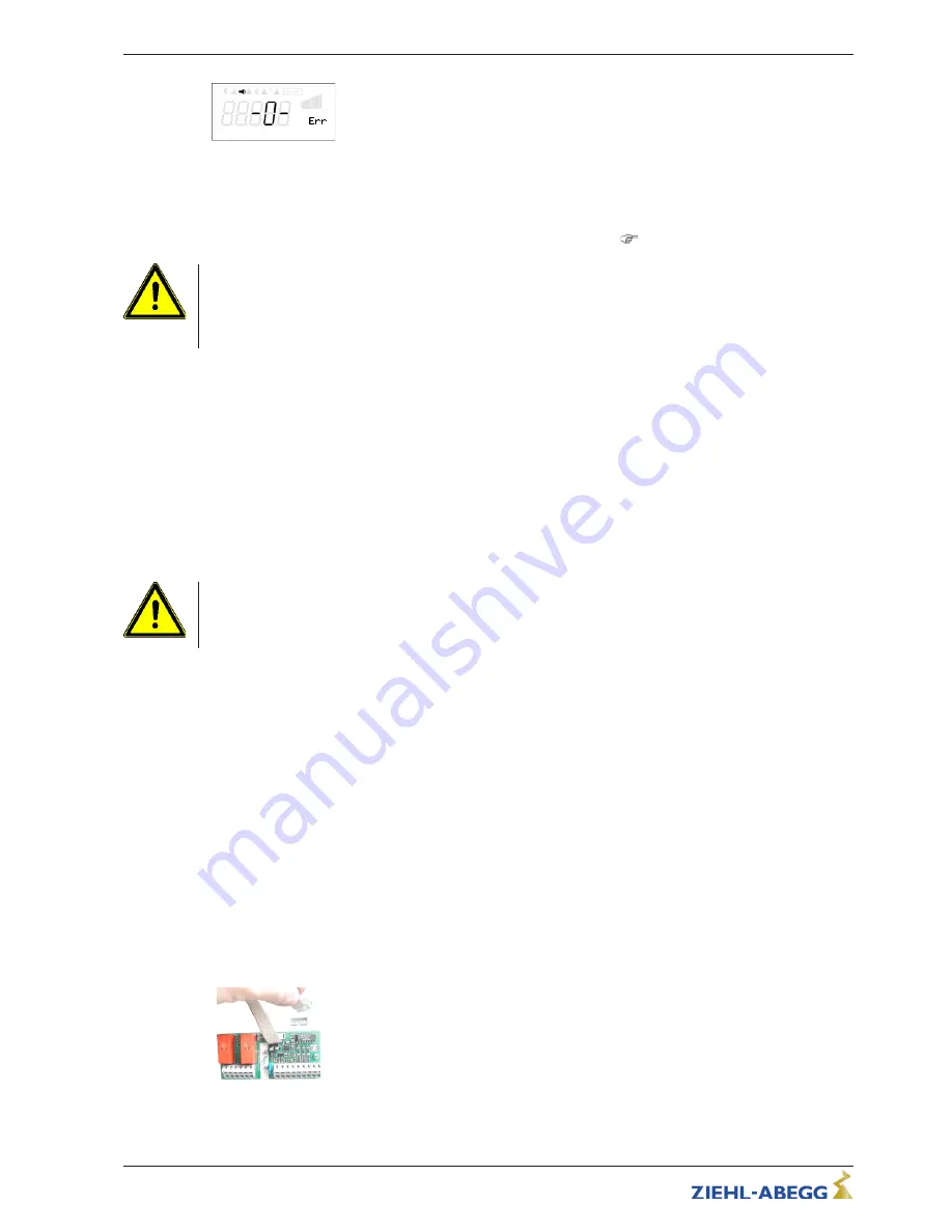
Motor fault
Display during motor fault
Possibilities for re-starting after the drive has cooled down terminals
“
TB/TP
”
bridged by:
•
By switching the mains voltage off and then on again.
•
By simultaneously depressing the three keys:
P
,
▲
,
▼
(if a fault is indicated).
•
By digital input for remote (enable ON/OFF) or by Reset-input (
IO Setup - Digital Inputs).
Attention!
•
An outside voltage may never be connected to the terminals
“
TB/TP
”
and/or!
•
If a bypass circuit is installed, or in the
“
100%
”
position on devices with a main switch, the motor
protection inside the controller has no function. In this case, additional motor monitoring may be
required.
5.8
Signal connection or sensor connection to analog inputs (Analog In 1, Analog In 2)
The unit has 2 analog inputs:
•
E1 Analog In = terminals
“
E1
”
/
“
GND
”
(Analog In 1)
•
E2 Analog In = terminals
“
E2
”
/
“
GND
”
(Analog In 2)
Ensure correct polarity when connecting; a 24 V DC power supply is integrated for sensors. For
sensors in two-wire-technology (4 - 20 mA signal), the connection is made on the
“
+24 V
”
and
“
E1
”
or
“
E2
”
terminals (the GND terminal is omitted). The connection is independent of the programmed
mode and from the sensor signal employed. Place the internal jumper for the external default signal in
the correct position. Factory setting 0 - 10 V (see Jumper for Input signal).
When triggering with a PWM signal (10 V) the ratio between the pull-up resistor and the internal
resistance of the open collector output must be considered.
Attention!
Never apply line voltage to analog inputs!
5.9
Analog output (0 - 10 V)
“
A1
”
The analogoutputs 0 - 10 V can be allocated with various functions (see IO Setup: Analog output
“
A
”
).
Connection to terminal
“
A
”
-
“
GND
”
=
“
Analog Out
”
(I
max
see technical data / connection diagram).
It is not permissible to connect outputs of several devices to each other!
5.10
Voltage supply for external devices (+24V, GND)
A voltage supply is integrated for external devices e.g. a sensor (max. current load see technical
data).
In case of overload or short circuit (24 V
–
GND), the external power supply is shut down (multi-fuse).
The device performs a
“
Reset
”
and continues operation.
•
It is not permissible to connect voltage outputs of several devices to each other!
•
It is not permissible to connect voltage outputs in the device to each other!
5.11
Add-on module type Z-Modul-B Part-No. 380052
The expansion module can be retro
fi
tted. This could be necessary if the analog and digital inputs and
outputs are not suf
fi
cient for certain applications. The board is easy to install into the device and is
connected with the control device via a plug. Program the additional inputs and outputs in
“
IO Setup
”
.
Add-on module type Z-
Modul-B
•
1x analogue input 0-10 V (R
i
> 100 k
Ω
) for external Set point
•
1x output 0 - 10 V (I
max
10 mA)
•
3x digital-inputs, Activation via
fl
oating contacts
•
2x relay outputs (contact load 2 A 250 V AC)
Operating Instructions
Fcontrol
–
model series FXDM
Electrical installation
L-BAL-E072-GB 1642 Index 008
Part.-No.
18/105


