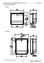
9 Enclosure
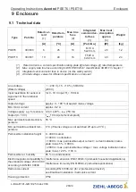
9.1 Technical data
Type
Part-No.
Rated cur-
rent
{1}
Rated tem-
perature
Max. line
fuse
{2}
Integrated
semiconduc-
tor fuse
{3}
Max. heat
dissipation
approx.
{4}
Weight
[A]
[
°
C]
[A]
[Part.-No.]
[W]
[kg]
PSET6
303630
6
45
10
M 10 A
5x20 mm
20
1.2
PSET10
303631
10
40
16
FF20 A
6x32 mm
40
2.3
{1}
Rated current se current speci
fi
cation rating plate @ rated voltage, @ rated temperature
{2}
Max. supply side line fuse according to DIN EN 60204-1 classi
fi
cation VDE0113 chapter 1
{3}
Integrated semiconductor fuse in device (no line safety switch)
{4}
At rated voltage, values for different speci
fi
cations on request
Line voltage
(Rated voltage)
1 ~ 230 V (-15...+10 %), 50/60 Hz
(230 V)
Input resistance for sensor or
signal set for the rotational
speed
for 0 - 10 V input: R
i
> 100 k
Ω
Output voltage
approx. 0 - 100 % of applied mains voltage
Min. motor current
approx. 0.2 A
Voltage supply e.g. for s24 V
±
20 %, I
max
250 mA
Output (0 - 10 V)
I
max
10 mA (short-circuit-proof)
Max. permissible ambient tem-
perature
55
°
C
Min. permissible ambient tem-
perature
0
°
C (if mains voltage is not switched off up to -20
°
C)
Permissible installation height
0...4000 m amsl
≤
1000 m: no limitation
> 1000 m: max. permissible output current = current indication name
plate minus 5 % / 1000 m
> 2000 m: max. permissible line voltage = max. voltage indication name
plate minus 1.29 % / 100 m
Permissible rel. humidity
85 % no condensation
Electromagnetic compatibility for
the standard voltage 230 / 400 V
according to DIN IEC 60038
Interference emission EN 61000-6-3 (domestic household applications)
Interference immunity EN 61000-6-2 (industrial applications)
Harmonics current
According EN 61000-3-2 (for a
“
professional device
”
)
see Electrical installation / harmonics current
Housing protection
IP54
Operating Instructions
Acontrol
PSET6 / PSET10
Enclosure
L-BAL-E141-GB 1925 Index 004
Part.-No.
20/24


