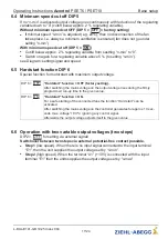
n-min
nM
100 %
1
t
n-max
1
2
05.02.2008
v_diagr_2stufen.VSD
"A1" (+10 V)
"E1"
nMotor
= "n-max"
nMotor
= "n-min"
1
2
05.02.2008
v_schalter_2stufen.VSD
7 Start-up
7.1 Prerequisites for commissioning
Attention!
1. You must mount and connect the device in accordance with the operating
instructions.
2. Double check that all connections are correct.
3. The mains voltage must match the information on the rating plate.
4. The rated current on the rating plate will not be exceeded.
5. Make sure that no persons or objects are in the hazardous area.
8 Diagnostics / Faults
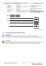
Operating states are indicated by both internal status LEDs by a
fl
ashing
code.
Code
Relay
K1
Explanation
Reaction of Controller
Adjustment
OFF
de-energized
terminals 11 - 12
bridged
No line voltage
In the event of a mains interruption
the unit switches
“
OFF
”
and auto-
matically
“
ON
”
when the voltage
has been restored.
Check line and internal controller
fuse.
ON
energized
Terminals 12 - 14
bridged
Normal operation without fault
Operating Instructions
Acontrol
PSET6 / PSET10
Start-up
L-BAL-E141-GB 1925 Index 004
Part.-No.
18/24


