9.10.2
Digital inputs
“
D1
”
/
“
D2
”
9.10.2.1
Menu overview
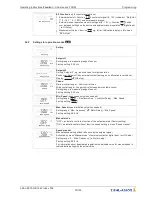
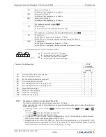
D1 Function
The digital inputs Digital In 1 (D1) and Digital In 2 (D2) can be allocated with various
functions.
Activation via
fl
oating contacts (a low voltage of approx. 24 V DC is connected).
D1 Inverting
Inverting
“
D1
”
and
“
D2
”
possible
D1 Busmode
With networking the digital inputs can be replaced by control over bus.
With mode of operation
4.03
pre-setting of
“
D1
”
and
“
D2
”
is
|
ON
|
.
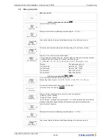
Attention!
Never apply line voltage to the digital input!
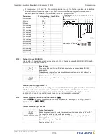
Function
Description
OFF
no function (factory setting)
1D
Enable (remote control)
“
ON
”
/
“
OFF
”
2D
External error
3D
“
Limit
”
ON / OFF
4D
Switch over
“
E1
”
/
“
E2
”
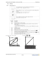
For mode speed controller
1.01
5D
Switch over
“
Set Intern1
”
/
“
Set Intern2
”
6D
Switch over
“
Intern
”
/
“
Extern
”
For modes as controller higher
2.01
5D
Switch over
“
Setpoint1
”
/
“
Setpoint2
”
6D
Switch over
“
Intern
”
/
“
Extern
”
7D
Switch over
“
automatic control
”
/
“
Speed manual
”
8D
Switch over control function (e.g.
“
heating
”
/
“
cooling
”
)
10D
“
Reset
”
11D
Setting Max. Speed
“
ON
”
/
“
OFF
”
12D
Motorheating ON / OFF (not for 1~ voltage controller)
13D
Reverse direction of rotation
“
right-hand
”
/
“
left-hand
”
(only for frequency inverter with 3 ~ out-
put)
14D
“
Freeze function
”
= maintain momentary modulation value
9.10.2.2
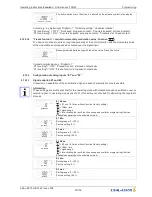
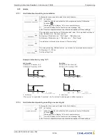
Enable ON/OFF function
|
1D
|
Remote ON/OFF (electronic disconnection) and Reset after a motor malfunction via
fl
oating contact.
The power section is electronically disconnected. Operation of the device is still possible after
pressing the
“
Esc
”
hotkey combination in switched-off condition. Signal- in and outputs remain active.
•
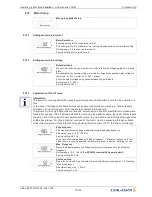
A programmed operating indicator relay (factory set
“
K1 function
”
=
|
1K
|
) reports the switch-off.
•
A programmed alarm relay (factory set
“
K2 function
”
=
|
2 K
|
) does not report the switch-off.
Operating Instructions
Fcontrol
–
model series FXDM
Programming
L-BAL-E072-GB 1642 Index 008
Part.-No.
61/105


