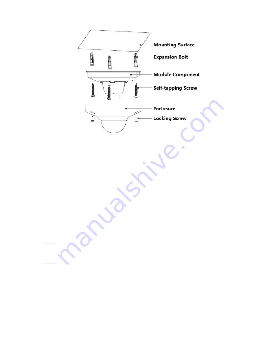
background image


Figure 2-2 

Step1 

Take out the installation position map and stick it on the mounting surface according to the 

monitoring area. 

Step 2 

Mark and dig bottom holes of plastic expansion bolts on the mounting surface, insert the 

expansion bolts into the mounting holes and lock them firmly. 

Note 


Please dig a “cable exit hole” on the surface according to the installation position map if you 
want to pull out the cable from the top of the installation surface when installing cable.  


You need to use the proper tool to open up the side port of the U-cable channel on the dome 

enclosure if you want to pull out the cable from the side exit of the cable channel when you 

are installing the device cable. And then you can pull out the cable from the side exit of cable 

channel on the pedestal. 

Step 3 

Adjust the device mounting pedestal to the proper position and then lead the cable into the cable 

Exit hole. 

Step 4 

Align the 

“TOP” direction of the device with the installation position map and then align the three 

screw fixing holes on the device pedestal with the three plastic expansion bolt fixing holes on the 

installation surface. Put the three self-tapping screws into the three plastic expansion bolts and 

secure them firmly, and then fix the dome on the installation surface.  


2.3  Connect Device Cable 

The installation process of waterproof connector for network port is shown in Figure 2-3. 

Note 

Содержание Dahua HD Mini

Страница 1: ...Dahua HD Mini Network Dome Camera Quick Start Guide Version 1 0 1 Zhejiang Dahua Vision Technology Co LTD...

Страница 2: ...roper handling or installation Environment Do not aim the device at strong light to focus such as lamp light and sun light otherwise it might cause over brightness or light marks which are not the dev...

Страница 3: ...or air blower to gently wipe it away If stained with grease or fingerprint use soft cloth to gently wipe the water drop or oil and wait till it is dry and then use oil free cotton cloth or lens cleani...

Страница 4: ...latory Information FCC Information 1 1 FCC conditions This device complies with part 15 of the FCC Rules Operation is subject to the following two conditions This device may not cause harmful interfer...

Страница 5: ...lation please open the package and check all the components are included Contact your local retailer as soon as possible if something is broken in your package Accessory Name Amount Accessory Name Amo...

Страница 6: ...ents 6 1 2 Dimensions 7 2 Installation 8 2 1 Install SD Card Optional 8 2 2 Fix Device 8 2 3 Connect Device Cable 9 2 4 Adjust Device Angle 10 3 Network Configuration 12 3 1 Device Initialization 12 3...

Страница 7: ...vice component and cable port function may differ according to different models please refer to the actual devices for details Figure 1 1 Figure 1 2 Please refer to Table 1 1 for detailed structure in...

Страница 8: ...wer input port Connect to DC 12V power input power Please be sure to power the device according to the instruction of device label Caution It may cause damage to the device if it fails to power the de...

Страница 9: ...e screws on the dome enclosure and then open the dome cover Step 2 SD card slot is shown in Figure 2 1 open the upper cover of SD card slot adjust the direction of SD card put the SD card into the car...

Страница 10: ...ll out the cable from the side exit of the cable channel when you are installing the device cable And then you can pull out the cable from the side exit of cable channel on the pedestal Step 3 Adjust...

Страница 11: ...ector on the network port and rotate it clockwise to lock the network port and waterproof connector firmly Step 4 Put the waterproof locking cover on the main body of waterproof connector and rotate i...

Страница 12: ...11 Figure 2 4 Hold the dome cover align it with the cable exit location and make the cover back in position Then use inner hex wrench to fasten three inner hex locking screws to complete installation...

Страница 13: ...dress of PC are in the same network segment In order to make the camera have access to network smoothly please plan available IP segment according to the actual network environment The following figur...

Страница 14: ...on the system begins to initialize the device means initialization succeeded means initialization failed Click the icon to check more details Step 7 Click OK to complete device initialization 3 2 Modi...

Страница 15: ...om the DHCP server Step 6 Click OK to complete modification of device IP address 3 3 Login WEB Interface Step 1 Open IE browser enter the modified camera IP address into the address bar and then press...

Страница 16: ...Zhejiang Dahua Vision Technology Co Ltd Address No 1199 Bin an Road Binjiang District Hangzhou PRC Postcode 310053 Tel 86 571 87688883 Fax 86 571 87688815 Email overseas dahuatech com Website www dahu...

Отзывы: