INFINITY ID2 INSTALLATION MANUAL.
Software Versions: PANEL 1.N & LOOP O.N
Approved Document No: GLT-211-7-1
Issue 1.9 Author: MG/NJ Date: 06/04/2016
PAGE 37
19. GENERAL FAULT FINDING
On the ID2 panel, Faults are divided into 2 types, “Faults” and “Device Faults”. Device Faults are any fault
associated with a particular Device on the system. Faults are everything else, EG, power supply etc. In the event
of multiple faults, the Faults are grouped together first, followed by the device faults. Next button will scroll to
next fault.
19.1 Common fault
This is a general indicator which lights whenever a fault is present. It doesn’t refer to a specific fault.
19.2 Zone contents fault finding
If the Zone contents are different to what was expected, then the probable causes are:-
1. Two or more devices may have the same address setting. This is referred to as a double address fault.
If this occurs all devices with the same address will answer at the same time. The panel will not be able
to understand the answer it receives.
NOTE: If a panel detects a double address, it will light the
LEDs of the devices with the problem. (NOTE: only detectors will light their LED. Sounders &
interface modules will not be indicated).
2.
There may be some reversed connections to devices (they are polarity sensitive). The Fyreye detectors
should be connected Zone + to L2, Zone – to L1IN. Other devices will have their polarity marked by
their connections.
If the panel reports any double addresses present, investigate these first as they are the easiest to find. The
panel will turn on the LED of any incorrectly addressed detector. (See 19.6 DOUBLE ADDRESS)
If there are still less devices than expected, check the missing addresses for correct wiring polarity. If in doubt,
contact your supplier.
If the wiring polarity is correct, check that there is no cable break on the loop. (If there is a break, the panel will
report the break after 60 seconds or so, and the break can be verified my measuring one side of the loop with a
DVM. The loop will be on for aprox 20 sec, and then will power just one side for 5 sec, then power both for 20
sec, then power just the other side for 5 seconds. (So the voltage should be monitored for aprox 50 sec for a full
cycle to confirm a cable break)
Some devices take a few seconds to power up, so may show as missing during the repeated Power Down /
Power Up cycle that occurs during a line break.
19.3 Zone faults
There are several reasons for the fault LED to light.
1. A device has the wrong configuration setting for the zone it is fitted to. (see section 7.3 Setting the device ID)
2. There is a cable break, or short circuit to devices in that zone,
3. A device has been removed from that zone
4. A device has been changed for one of a different type
5. There is a double address in this zone (see previous section)
6. A device in that zone is communicating a fault condition to the panel.
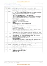
The LCD will show Device Fault, the user label, and the address
Of the fault. Pressing enter will bring up the View Device screen
for the device showing fault. This will give more information about the
fault.
In this example, the detector is removed. IE the sounder base cannot see the
Detector.
This could either be a removed detector, A detector that is not correctly seated in
Its base or an incompatible detector has been fitted.
Check the device has not been removed
Check that there is power to the base. Check Device ID switch hasn’t been changed
(compare to system set-up chart). Check that the base contacts are clean and
free from dirt & corrosion. Try a replacement detector head.
*** Device Fault ***
1 of 1
Floor 1 Room 101
Zone:01 Ad:001
Optical Missing
Fault
Zone:01 Ad:001

